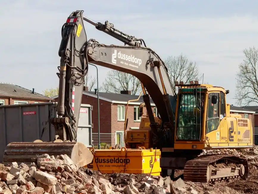
A new excavator leaves the factory as a verified machine and arrives on site as an unproven assembly, so the testing and commissioning procedure is the contract that closes the gap between the two. The objective is simple: prove the machine meets the Owner's Project Requirements (OPR) and Basis of Design (BoD) before a single bucket is loaded, and document every deviation along the way [S1][S2].
The four commonly cited phases are initial inspection and setup, testing, performance verification, and final handover checks, with each phase gated by a signed checklist rather than a calendar date [S1][S2]. For a 20–30 t hydraulic excavator, plan 2–4 working days for cold commissioning on a prepared bench, plus 1–2 days of site acceptance with the bucket under load.
Pre-arrival paperwork: OPR, BoD, and the FAT dossier
Commissioning starts months before the truck rolls, in the documents that define what "good" looks like: the OPR (owner-written performance goals) and the BoD (engineer-written design basis), supported by an Inspection and Test Plan (ITP) and a Factory Acceptance Test (FAT) report [S2][S3]. The FAT verifies that the excavator meets design criteria at the OEM yard, through electrical measurements, operational tests, and simulated load scenarios, and any deviation is documented, investigated, and rectified before shipment [S3].
For an excavator specifically, the FAT dossier should already record: engine power curve, hydraulic pump displacement and rated pressure (typically 30–35 MPa working / 37–42 MPa relief on a 20-ton class machine), track tension, slew bearing torque, and the serial numbers of major assemblies (engine, pumps, controller, slewing ring). If the FAT report is missing or the pump serial does not match the packing list, halt acceptance on arrival; that single mismatch has triggered multi-week warranty disputes on Tier-2 builds.
Mechanical completion on site
Once on site, mechanical completion is the verification that the machine is physically intact, properly assembled, and ready for energisation: tracks tensioned, idlers greased, hydraulic hoses routed without twist, fluid levels topped, battery connected with correct polarity, and safety decals in the operator's language [S1][S3]. This is the cheapest gate to pass and the easiest to skip, and skipping it is the most common root cause of first-day breakdowns, including hydraulic cavitation from under-filled tanks and track derailment from wrong idler adjustment.
Use a written QA/QC checklist rather than a verbal walk-down; a clean visual hides loose track bolts and a slow hydraulic leak for the first hour of operation. Improper mounting or installation is one of the two most-cited commissioning failure modes, alongside the integration step that follows, and it directly causes vibration, premature bearing wear, and reduced service life [S2].
Hydraulic and electrical cold commissioning
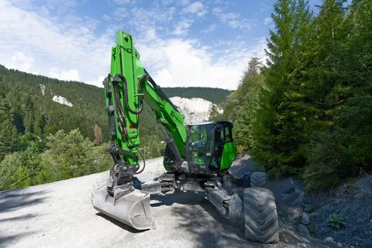
Cold commissioning energises the machine with no load: verify engine cranking rpm, confirm pilot pressure (typically 3–5 MPa on modern excavators), bleed air from each actuator, and walk the full pilot signal range on boom, arm, bucket, swing, and travel [S1]. At the same time, validate the controller: the excavator ECU should accept key-on self-test, no active DTCs, and matched CAN-bus addresses between the display, the engine ECM, and the hydraulic controller; an address clash is a frequent cause of intermittent no-crank faults on new builds.
Electrical safety follows the same gate logic used across heavy plant: lockout-tagout the battery before any harness work, verify insulation resistance on the AC generator circuit (≥1 MΩ at 500 V for a 24 V system, per typical OEM specs), and confirm emergency stop wiring trips the fuel solenoid within the OEM-specified millisecond window [S3]. The construction machinery and equipment category is broad, but the electrical isolation discipline is identical across excavators, loaders, and crawler cranes.
Functional no-load and full-load testing
No-load testing exercises every function at slow speed: full boom-up/arm-in/bucket-curl, 360° swing left and right, high/low travel in both directions, and auxiliary hydraulic flow (if fitted) at idle and rated engine rpm. The pass criteria are smoothness, full-stroke reach without cylinder bottom-out, and oil temperature staying inside the green band on the gauge, typically 50–80 °C after 15–20 minutes of continuous cycling [S1][S4].
Full-load testing is where the FAT performance claims are actually proven on site: dig cycles in a calibrated sand pile, lift tests at the rated load chart radius, and a sustained 30-minute swing-under-load to verify hydraulic steady-state temperature. This is the test that catches pump wear, slewing-ring backlash, and track-motor leakage that the FAT on a clean yard floor could not expose, and the recorded curves go into the Site Acceptance Test (SAT) report [S3][S4]. For a frame of reference on how the components actually behave under load, see how a hydraulic excavator actually works, from engine to bucket; the SAT is the moment that description is checked against numbers.
Safety systems, calibration, and compliance
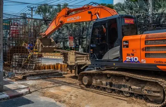
Safety testing covers the systems that protect the operator if a mechanical test goes wrong: emergency stop, ROPS/FOPS structure integrity (visual + torque check on the cab mounting bolts), overload warning, neutral-start, two-block avoidance on lifting attachments, and reverse alarm [S3]. In the United States, NFPA 70E governs electrical safety in the workplace and is the de facto reference for energised-work boundaries during commissioning, even though no standardised commissioning format is explicitly mandated [S4].
Calibration is its own sub-gate: the pressure transmitter feeding the load-moment indicator is re-zeroed on site, hydraulic pressure gauges are cross-checked against a calibrated reference, and any factory set-points (engine derate thresholds, hydraulic relief, accumulator nitrogen pre-charge) are recorded before the machine is released to the operator. If a sensor was factory-calibrated in a different ambient condition, expect a 1–3% drift on the display versus the reference instrument on day one, and re-zero it rather than accepting the offset.
Documentation, training, and handover
Commissioning is not complete until the documentation is signed and the operator is trained on the as-built configuration, not the sales brochure. The handover pack should include the OPR/BoD, the ITP, the FAT and SAT reports, a snag list with closure dates, the as-built hydraulic and electrical schematics, and the preventive-maintenance schedule aligned to the operating conditions on site [S1][S2][S4].
Operator and maintenance training is the final gate, and historically it is the gate that gets squeezed when the project is behind schedule, which is why retro-commissioning, the re-test of an existing machine, is a recognised service line in mature fleets rather than a corner case [S4]. For a deeper look at how the underlying powertrain behaves once it leaves the commissioning pad, the bulldozer working principle, covering engine, hydraulics, and track traction, gives a useful comparison point since the hydraulic and undercarriage logic mirrors a crawler excavator.
Trackable signals for the next 6 months: (1) whether Tier-4 Final / Stage V engine ECUs are exposing a closed-aftertreatment warm-up window that the SAT does not currently exercise, and (2) whether OEM telematics are being used to record the SAT load curves as a baseline, so warranty claims on pumps and slewing rings are judged against the as-delivered performance rather than the brochure.