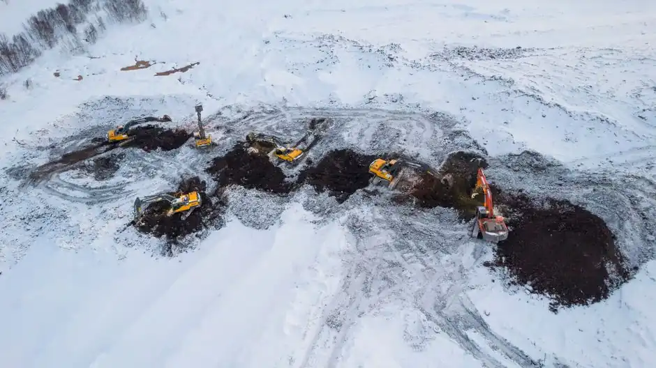
A 20 tonne excavator on standard 600 mm track shoes and 3.355 m of tumbler-to-tumbler contact length lands at 48.7 kPa (7.06 psi) of static ground pressure, per a worked example published 2026-07-10 [S3], almost identical to the 45 to 52 kPa (6.5 to 7.5 psi) range cited in the omnicalcengine reference data for a 20-22 tonne class machine [S1].
Ground pressure is not a single number, it is a load distribution problem governed by the standard physics relationship P = F / A [S3][S4]. For a tracked excavator, A is the sum of both track footprints, each footprint = shoe width × ground contact length, and F is mass × g, where g = 9.80665 m/s² [S3]. The two practical levers an operator or planner can change on a given machine are track shoe width and ground contact length (which is fixed by the undercarriage geometry, tumbler center to idler center) [S1].
Formula chain: from operating weight to kPa, PSI, and kg/cm²
The base relationship is P = F / A, with F = m × g when only mass is known [S3]. Three unit presentations are useful on a spec sheet, and the omnicalcengine reference lays them out cleanly [S1]:
Total Track Contact Area = Number of Tracks (2) × Track Shoe Width × Ground Contact Length [S1].
Pressure (kPa) = [Weight (kg) × 9.80665] / [Contact Area (m²) × 1000] [S1].
Pressure (kg/cm²) = Weight (kg) / Contact Area (cm²) [S1].
Pressure (PSI) = Weight (lbs) / Contact Area (sq inches) [S1].
For unit sanity: 100 kPa = 14.504 psi = 1.0197 kg/cm², which is why the same machine reports as ~48.7 kPa, ~7.06 psi, and ~0.497 kg/cm² across these three systems [S3]. A tracked machine in the 20 tonne class sits well below a passenger car tire (200 to 240 kPa, 29 to 35 psi) and roughly an order of magnitude below a loaded truck tire (600 to 900 kPa, 85 to 130 psi) [S3]. For a broader view of how tracked undercarriages compare with wheeled plant and other heavy equipment footprints, the math is identical, only the contact patch changes.
Typical ground pressure bands: standard vs LGP vs wheeled plant
Standard 20 to 22 tonne tracked excavators on 600 mm shoes run 45 to 52 kPa (6.5 to 7.5 psi) static [S1]. The Calculator Academy 2026-07-10 reference table widens the standard tracked excavator band to 45 to 80 kPa (6.5 to 12 psi) and adds a Low Ground Pressure excavator band at 25 to 45 kPa (3.6 to 6.5 psi) [S3].
Low Ground Pressure (LGP) configurations get there with extra-wide track shoes, typically 800 to 900 mm versus the standard 600 mm, plus longer track frames and a wider gauge, cutting static pressure by 30 to 40% versus a standard undercarriage of the same machine mass [S1]. LGP bulldozers in the same data set reach 25 to 35 kPa (3.6 to 5.0 psi) and will walk across soft mud that would immobilise a standard gauge [S1].
Main battle tanks, included as a useful extreme in the same table, sit at 95 to 110 kPa (14 to 16 psi), roughly double a standard excavator [S3]. Wheeled construction trucks, by contrast, run 200 to 500 kPa (30 to 70 psi) per tyre, the reason trucks sink on soft ground where an excavator of similar mass walks across [S1][S3].
What soil can actually take: allowable bearing capacity benchmarks
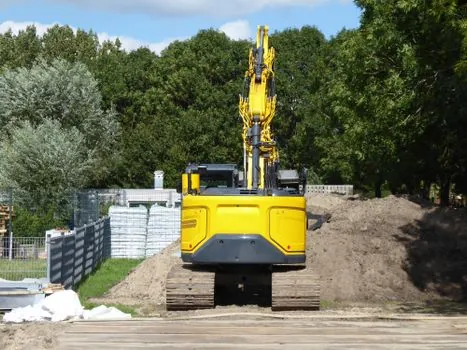
The static pressure number is only useful when compared against allowable soil bearing capacity, otherwise the operator is just dividing mass by area for no reason. The Calculator Academy 2026-07-10 table gives these safe bearing bands [S3]:
Soft clay or peat: 25 to 50 kPa (3.6 to 7 psi).
Firm clay: 75 to 150 kPa (11 to 22 psi).
Loose sand or gravel: 100 to 200 kPa (14 to 29 psi).
Compact sand or gravel: 200 to 600 kPa (29 to 87 psi).
Soft rock: 600 to 2000 kPa (87 to 290 psi).
The omnicalcengine reference uses a compressed 3-band version of the same scale: soft clay/peat 25-50 kPa, soft silt/sand 50-100 kPa, compacted gravel/rock >300 kPa [S1]. The two scales agree on the lower bound, soft clay/peat starting at 25 kPa, and that is the working number a planner uses as the floor for a temporary works platform design. The Federation of Piling Specialists' Rig Track Pressure Calculation Tool, dated 2016-06-09 in its public guidance, applies the same logic specifically to piling rig undercarriages and the working platforms they sit on [S7].
Static vs dynamic: why 70/30 asymmetric loading changes the answer
The static calculation gives a mean contact pressure, not a peak. During heavy digging, lifting, or travelling downhill, the load on the track toes can rise to 200% to 300% of the static mean [S1]. When an excavator swings its upper structure 90° to the side, counterweight and boom loads shift the centre of gravity, and one track can carry up to 70% of total machine weight, asymmetric track loading that the static mean does not see [S1].
The Diggy calculator release notes (2026-02-01) flag the same point directly: the tool computes average contact pressure only, actual pressure distribution under tracks and tyres is non-uniform, and peak pressures at edges can be significantly higher [S4]. Both reference sources converge on the same practical rule: a working platform or crane mat must be sized to peak loading conditions, not the static mean.
Spreading the load: crane mats, working platforms, and outrigger pads
When a tracked machine or crane outrigger exceeds the allowable soil bearing, the standard fix is a mat or working platform that enlarges A in P = F / A. A worked example in the Calculator Academy reference: a 250 kN outrigger on soft clay rated at 50 kPa needs 250,000 / 50,000 = 5 m² of mat, a square pad at least ~2.24 m on a side [S3].
Timber or steel crane mats under crawler cranes typically cut peak ground bearing pressure by 50% to 75% versus direct track loading on the same soil [S1]. For working platform design, Diggy points to BRE BR470 and CIRIA C774 as the UK references that handle load spread, dynamic effects, and platform thickness [S4]. The Federation of Piling Specialists' guidance and rig track pressure tool apply this same spread-the-load logic to piling rigs on temporary works platforms [S7].
Calculator tool landscape in 2026: what each one actually does
Seven public ground pressure calculators were active or updated within the 6 months to 2026-09-25. They share the same base physics but differ in workflow and depth: [S3]
omnicalcengine.com: Tracked-machine focus, returns kPa, PSI, and kg/cm² from operating weight plus shoe width and tumbler-to-tumbler length, with the widest range of excavator/bulldozer/crawler crane reference data including LGP bands and dynamic load factors [S1].
Calculator Academy (2026-07-10 update): three modes (Pressure, Footprint, Solve) sharing one formula, full unit set (Pa, kPa, psi, bar), track/tyre/mat/pad footprint builder, plus the worked 20 tonne example at 48.7 kPa and the soil bearing capacity table cited above [S3].
Diggy (2026-02-01 release): equipment presets from mini excavator to HGV, custom value override, and direct comparison to allowable bearing capacity with explicit pointer to BRE BR470 and CIRIA C774 for platform design [S4].
calculatorgek.com, savvycalculator.com, everycalculators.com: lighter-weight tools, weight plus contact length plus contact width, output in Pa/kPa/psi/psf; useful for quick sanity checks but no equipment-specific presets or soil bearing comparison [S2][S5][S6].
Federation of Piling Specialists Rig Track Pressure Calculation Tool (R2.0, public version dated 2016-06-09): single-purpose tool for piling rig undercarriage pressures on working platforms, the reference that the Diggy pointer and the omnicalcengine LGP discussion both align with [S7].
Selection criteria: which tool matches which job
For an excavator or dozer undercarriage on a soft-ground site where you need kPa and PSI for a permit submittal, omnicalcengine gives the most directly usable output and the most complete reference data set [S1]. For a multi-mode workflow where you might know pressure and need area, or know area and need force, Calculator Academy's Solve tab is the most flexible single form, and the 2026-07-10 update includes both the worked excavator example and the soil bearing table in one place [S3]. For a UK piling or temporary works platform check, the FPS tool and the BRE BR470 / CIRIA C774 references are the right starting point [S4][S7].
For outrigger pad sizing on a crawler crane pick, the same P = F / A math applies, but the relevant peak load is the outrigger reaction, not the total machine weight, and the Calculator Academy 250 kN / 5 m² worked example is the cleanest demonstration of the logic [S3]. For broader machine-on-ground footprint decisions including wheeled and tracked plant, the same formula chain holds and the only question is which contact area to plug in. Where bucket tear-out or arm crowd force, rather than bearing pressure, is the controlling limit on a soft site, see this excavator bucket breakout vs arm crowd force spec comparison for the matching duty-side spec map.
Two trackable signals for the next planning cycle: the Federation of Piling Specialists rig track pressure tool, public version dated 2016-06-09, has not been re-versioned in the public guidance as of 2026-09-25 [S7], and Calculator Academy last updated its ground pressure calculator on 2026-07-10 [S3]. Both remain the most current public references for their respective scopes.
Spec-level background on the components involved: earth ground tester.