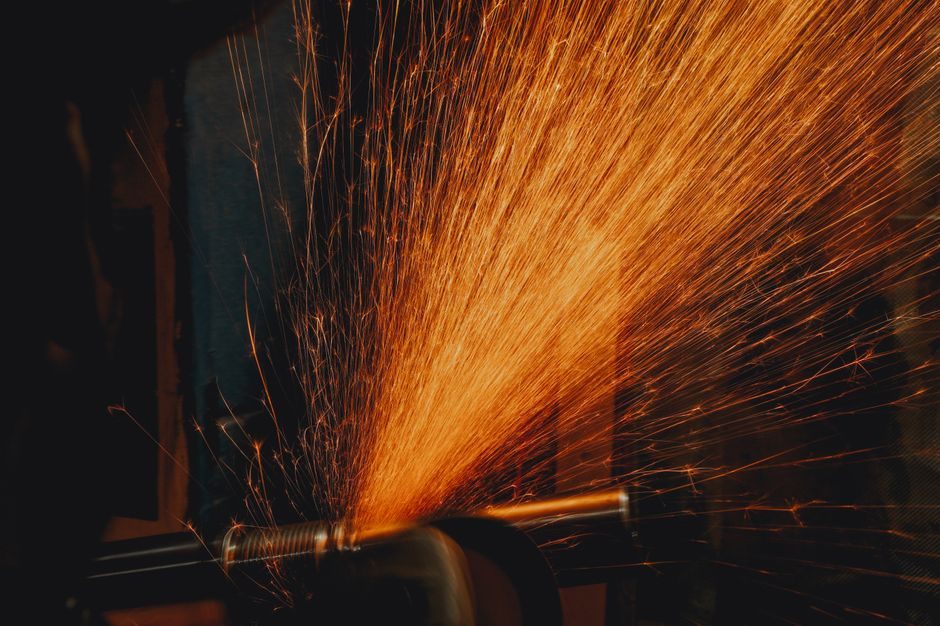
A bench or stand-mounted fettling grinder installation succeeds when the rated wheel speed (m/s) printed on every blotter matches the spindle RPM stamped on the machine nameplate, and the declared bore matches the arbor — a mismatch on any one of those three is the single most common cause of wheel burst on first spin-up [S3].
This guide walks the install sequence a process engineer runs on a receiving dock: foundation/bench check, electrical and dust-extraction tie-in, wheel mounting with the torque-wrench method, then a documented no-load and loaded commissioning pass before the grinder is signed over to the fettling bay [S1] reference framing on site-installed equipment commissioning.
Pre-Install: Foundation, Bench Mass, and Floor Loading
A pedestal fettling grinder should sit on a concrete plinth rated for the combined static load of machine + heaviest expected workpiece; portable bench units require a bench of minimum 25 mm thick steel-reinforced top, with the grinder bolted through using M12 grade 8.8 fasteners torqued to 80–90 N·m so the wheel plane does not walk under side load [S3] machine-layout dimensional reference for a comparable grinder-class unit.
Floor flatness under the pedestal feet must hold ≤ 2 mm/m; shim with steel shims only — never composite or nylon — and grout the anchor pockets with non-shrink cementitious grout after the hold-down bolts are tensioned. Vibration isolation is not optional: a free-standing fettling grinder running a 36-grit cup wheel will couple structurally into the foundry floor and transmit into adjacent fettling grinder workstations if the plinth mass is undersized. Allow minimum 1.0 m of clearance to any non-protected operator station on either side of the wheel plane.
Electrical Tie-In: Voltage, Phase, and Inrush
Three-phase 400 V / 50 Hz units draw 3–7 kW depending on the wheel diameter; single-phase 230 V portable versions cap around 1.5–2.2 kW and must be fed from a dedicated MCB (typically 16 A C-curve) with a 30 mA RCD on the socket outlet. Conductor cross-section is sized so voltage drop from the distribution board to the machine isolator does not exceed 4% at full load — that fixes 2.5 mm² copper for runs up to ~25 m on a 16 A circuit, and 4 mm² for 25–40 m. [S3]
Wire the lockable isolator within 1.5 m of the grinder and within the operator's line of sight, then run a separate earth conductor of ≥ 6 mm² cross-section bonded back to the main earth bar — daisy-chaining grinder earths through adjacent machine steelwork is a recurring audit finding. Cable entries into the grinder body must use IP54 or better glands where the cable exits a foundry wash-down zone; standard PG11 or M20 entries are typical on European-built units and accept 8–13 mm OD cable. For dust-laden atmospheres near the wheel, route power in rigid conduit or use an armoured cable with an overall PVC sheath rated to 70 °C.
Dust Extraction: Airflow at the Hood Is the Audit Gate

An unguarded fettling grinder throws respirable crystalline silica at concentrations well above 0.025 mg/m³ within 2 m of the wheel if no extraction is fitted, so the extraction hood and duct must be commissioned before the first workpiece is dressed. Target transport velocity in the duct is 18–22 m/s for silica-bearing fines; lower velocities drop load out in the bend, higher velocities wear the elbow walls and starve the wheel-side hood of capture volume. [S3]
Capture velocity at the hood face should read 15–25 m/s for a typical 350–400 mm wheel, measured with a hot-wire anemometer at the hood opening with the wheel running but no workpiece. The extraction branch must include a quick-release blanking cap or auto-damper so a single grinder can be isolated while neighbours stay live. Tie the extraction starter into the grinder's run-permissive interlock so the wheel cannot spin up unless the extractor fan is proved on by a differential pressure switch (typical set point 1.0–1.5 kPa across a clean filter).
Wheel Mounting: Blotters, Flanges, and Torque
Wheel diameter, thickness, and bore printed on the blotter sandwich must all match the machine nameplate and the spindle arbor; the maximum permissible operating speed (m/s) printed on the wheel must be ≥ the spindle's no-load peripheral speed with a 1.5× safety margin for portable / non-pedestal units. Use only the manufacturer's matched flanges — flange diameter must cover ≥ 1/3 of the wheel diameter for plain grinding wheels, and the bearing surface must be flat, clean, and free of burrs. [S3]
Insert a compressible blotter (typically 0.5–1.0 mm cellulose or rubber-cork) on each side of the wheel, then finger-tighten the arbor nut before applying the final torque with a calibrated wrench; do not hammer the wheel onto the arbor. After 30 seconds of no-load running, re-check the torque — settling of the blotter will release clamp load and is the root cause of many in-service wheel slip marks. Wheel guards must be closed to within 6 mm of the wheel periphery on pedestal grinders and ≤ 3 mm on bench units before any workpiece is touched, with the guard tongue adjusted to the workpiece size each shift.
Commissioning: No-Load, Loaded, and Acceptance
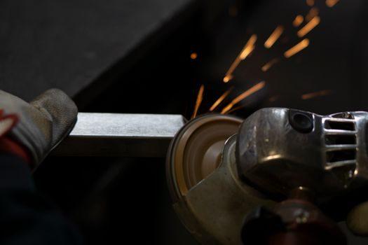
Run the grinder no-load for 5 minutes; the wheel must run true, without audible rub on the guard, with bearing-housing temperature stabilising below 60 °C (a touch-test on a stopped housing is enough for a field check). Then run a 3-minute loaded pass on a piece of known-hardness scrap — current draw should sit within ±10% of the nameplate FLA, and the extraction hood must still pull 15 m/s at the face with a workpiece in place. [S3]
Document the three readings (no-load amps, loaded amps, hood face velocity) on the install sheet before handing the unit over; these become the baseline for the next shift's daily check. Where the grinder feeds a downstream angle grinder hand-off station, confirm the interlocked extraction branch carries the same transport velocity and that the floor-grinder cleaning regime (sweep, not blow-down) is locked into the area SOP. Sign the install sheet, file the commissioning record, and only then is the machine released to production.
When NOT to Self-Install: Escalation Triggers
Escalate to the OEM or a qualified electrical contractor if the spindle RPM does not match the wheel m/s rating with the 1.5× margin, if the foundation plinth shows > 3 mm/m out-of-flat, or if the extraction branch cannot meet 18 m/s transport velocity with the duct length and bend count as installed — adding a third elbow to chase the number will not fix it, a larger fan or a re-routed duct will. Replace (do not repair) any wheel that has been dropped, exposed to moisture, or stored past its shelf life. [S3]
Track these signals between audits: extraction static pressure drift on the filter gauge (a rising baseline indicates blinded media and falling capture velocity), an uptick in wheel consumption per shift (a sign of glaze loading or wrong-grade selection), and any guard adjustment that has been re-set more than twice in a quarter — at that point the guard geometry is wrong and the wheel guard, not the operator, is the spec that needs review. Next nodes to watch for in the floor grinder retrofit plan are extraction branch balancing and abrasive-grade standardisation across the fettling cell.
Background reading: Variable Speed Drive Installation: Cabinet Prep, Wiring, and 4-Parameter Start-Up.