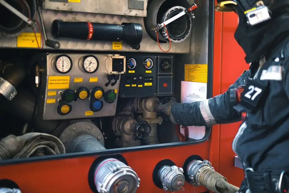
Firefighting and emergency-system E-Stops are specified against three binding references: ISO 13850 (mechanical behaviour, colour, shape), IEC 60947-5-5 (electrical ratings of the safety contact block), and the Machinery Directive 2006/42/EC for installations in the European Economic Area [S3][S5][S6].
For a fire pump control panel, an emergency power unit, or a smoke-extraction drive, the typical minimum is a 40 mm mushroom-head pushbutton, red actuator on yellow background, mechanical latching, ≥IP65 housing, and a positively-driven (force-guided) contact block rated for AC-15 / DC-13 inductive loads [S3][S5][S7].
What ISO 13850 and IEC 60947-5-5 actually require
ISO 13850 mandates that the actuator be coloured red with a yellow background, that pressing it latches mechanically so the circuit cannot re-energise on its own, and that reset be a deliberate manual action, preferably twist or pull rather than a key [S3][S5][S7]. IEC 60947-5-5 sets the electrical endurance and contact-block performance for the safety function, including the requirement that the device withstand the inrush of motor loads typical of fire pumps and ventilation fans [S5][S7]. Compliance with both is the baseline for any emergency stop going into a fire-protection cabinet.
Where the fire E-Stop is part of a Category 1 controlled stop (power removed only after a controlled ramp-down) versus a Category 0 unassisted removal of power, the risk assessment on the host machinery drives the choice; both are explicitly permitted under ISO 13850, but the safety relay or contactor arrangement behind the button must match the chosen category [S2][S7].
IP rating, IK impact, and the washdown / outdoor problem
Indoor fire pump rooms and electrical rooms usually call for IP65 as the working minimum, while outdoor cabinet installations, tunnel fire systems, and offshore modules generally step up to IP66 or IP67; food-line or hose-down zones on petrochemical sites commonly demand IP69K plus a NEMA 4X equivalent [S4][S7]. The IP code's first digit (0–6) covers solids, the second (0–9K) covers liquids, and for an E-Stop the second digit is the one that protects the contact block against hose-directed water during a fire event or post-incident washdown [S4].
IK impact rating is paired with IP in the same enclosure spec, and ISO 13850 expects the actuator to survive the rough handling typical of an emergency: gloves, tools, even a boot in a panic stop. For tunnel and shipboard applications, an IK08 or IK10 housing around a stainless-steel mushroom head is the practical floor [S7].
Mounting height, placement, and reset method
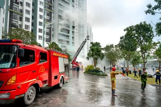
Hand-operated E-Stop actuators on a fire panel or pump skid should sit between 0.6 m and 1.7 m above the access level so they remain reachable for a kneeling responder in full PPE [S7]. ISO 13850 explicitly discourages key-disengage reset devices because a missing key at the wrong moment can lock a system out; twist-to-release and pull-to-release are the preferred reset mechanisms on most modern fire-panel builds [S5][S7].
For a fire pump room with two entry doors, an emergency stop button at each door plus one at the controller face gives three independent initiators; cable runs route through fire-rated conduit and the contact blocks are wired as dual-channel to the safety relay, allowing cross-fault detection at Performance Level d (PLd) per ISO 13849-1, which is the level most industrial E-Stops are designed to meet [S7][S8].
Fire-system specific options: illuminated, guarded, and twist-release
Three variants dominate fire-protection cabinets: a guarded mushroom head (with a yellow shroud that prevents accidental strike but allows palm press), a non-illuminated latching head (lowest cost, used inside the panel), and an illuminated latching head with a separate status indicator that confirms the button is armed [S3][S4]. The illuminated option draws an additional 24 V DC or 120/230 V AC supply and is the version spec'd where the responder must identify the E-Stop from across a dimly-lit pump room filled with smoke [S3].
Twist-release reset is the default for indoor fire panels; pull-release is preferred on outdoor enclosures where gloved, possibly wet, hands work the actuator. Key-release models are reserved for sites where inadvertent reset could re-energise a system that responders are still inspecting, for example a high-voltage fire pump motor after a confirmed incident [S3][S5][S7].
Comparison: fire-panel E-Stop variants on four selection criteria
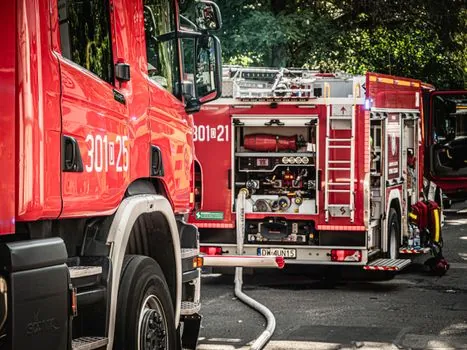
Choosing between the three common fire-protection E-Stop builds comes down to four criteria: actuator type, ingress protection, reset mechanism, and intended environment. The table below lines up the three main options process engineers compare for a new fire pump skid or smoke-control cabinet. [S7]
1) Standard latching mushroom (red/yellow, IP65, twist release, indoor fire pump room): cost lowest, contact block rated to IEC 60947-5-5, fits a 22.5 mm or 30.5 mm panel cutout, suited to controlled-access electrical rooms.
2) Illuminated latching mushroom (red/yellow, IP66, twist release, indoor/outdoor fire panel): adds 24 V DC indicator circuit, slightly deeper behind-panel depth, allows status confirmation from up to 10 m in a dim pump hall, common on large commercial fire-panel builds.
3) Heavy-duty stainless mushroom (red/yellow, IP67 or IP69K, pull or key release, outdoor / tunnel / offshore): 316L stainless head, IK10 housing, suited to washdown zones, marine decks, and petrochemical modules, highest cost but the only option that survives hose-test, salt spray, and rough gloved handling [S3][S4][S7].
Limits, failure modes, and what the spec must not assume
An E-Stop is a safety component, not a process isolator: its job is to stop, not to provide energy isolation for lockout/tagout; a separate disconnect switch is still required upstream of the fire pump or smoke fan to meet NFPA 70E lockout practice [S7]. Mixing an E-Stop with a normal start/stop pushbutton on the same contact block is a common field failure mode; the safety contact block must be force-guided (positively driven) so a welded NO contact cannot simultaneously close the NC contact, which would defeat the safety function [S5][S7].
For flammable atmosphere zones, the enclosure may need to be ATEX or IECEx certified for the surrounding gas group; the button itself is non-arcing in normal operation, but the housing and cable entries still fall under the zone classification rules. Power-supply selection for an illuminated variant should not backfeed through the safety contacts, because doing so can hold the contacts in and prevent the latch from releasing on a real stop event [S5][S7]. The emergency light and emergency rescue systems on the same cabinet should be on a separate, non-E-Stopped circuit so evacuation signage stays lit when the pump is deliberately shut down.
Tracking signals and the next decision node
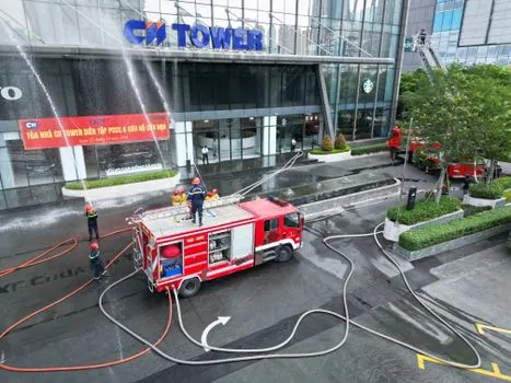
Two trackable signals for the next spec cycle: the IEC 60947-5-5 maintenance amendment cycle, which historically tightened mechanical endurance figures for safety contact blocks, and the broader harmonisation between ISO 13850 and the Machinery Directive 2006/42/EC revision tracked by the European Commission. Engineers should also re-check the fire-pump controller UL 448 / FM 1321/1323 listing against the chosen E-Stop actuator, since fire-pump controllers in the U.S. market have their own E-Stop requirements separate from ISO 13850. For sites that already use flow-meter loops on the fire-water main, the E-Stop wiring should be tested under simulated flow conditions, because the inrush of a fire pump at full demand is the worst case the IEC 60947-5-5 endurance figures are designed to cover. Specs for this application pair naturally with the kind of structured decision criteria used in Stepper Motor Selection for Chemical Processing: Spec-First Criteria and Single Girder Crane Selection for Agriculture: Spec-First 2026 Guide, where the rule is the same: lock the standard first, then match the actuator, the IP code, and the reset to the environment. [S5]