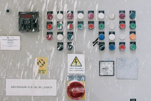
An emergency stop for electrical work is a fail-safe, manually actuated control device that uses positive-break normally closed contacts to cut power the instant the red mushroom button is pressed, with reset only by deliberate twist, pull, or key release.
For electrical-installation work the spec reduces to four hard numbers: ISO 13850 / IEC 60947-5-5 compliance, panel cut-out 22.5 mm or 30.5 mm, ingress protection IP65 or higher, and a contact block rated for AC-15 / DC-13 utilisation category at the actual control voltage. Anything short of those four is a stop button, not a safety stop [S1][S2][S3].
Standards that govern an electrical-work E-stop
ISO 13850 (2024 revision) is the overarching design standard for emergency-stop devices on machinery: it mandates the red mushroom head on a yellow background, direct mechanical action (no software in the safety path), and latching that holds the contacts open until a deliberate reset [S1][S3]. For low-voltage switchgear the contact block must additionally satisfy IEC 60947-5-5, which adds the electrical requirements for the auxiliary contacts used in the safety circuit [S2][S3].
On energised electrical panels the surrounding enclosure has to meet IEC 61439 for assemblies, while outdoor or washdown sites require at least IP65 from the front face and IP2X from the rear to keep creepage and clearances safe during a stop event [S3]. The North American equivalent for the device itself is UL 508 / NFPA 79, and machines bound for the European market carry the CE mark under the Machinery Directive 2006/42/EC [S1][S3].
Contact topology and positive opening
Every E-stop for electrical work must use a positive-break NC contact block: when the button is pressed, or when a wire breaks, the NC contact is mechanically forced open, not merely de-energised, which guarantees a stop even if the contact is welded [S2]. A 1NC + 1NO block is the most common stock configuration and is sufficient for most motor-starter safety chains [S1][S2].
Higher-risk circuits (servos, robot cells, battery storage) use 2NC blocks wired in series so a single contact failure cannot bypass the stop. A 2NC + 1NO arrangement is also the standard pattern for combination panels where a status lamp on the NO contact mirrors the E-stop state to a PLC or indicator [S3]. Self-monitoring force-guided contacts (IEC 60947-5-1, designated
Mounting, sealing, and actuator style

Panel-mount E-stops for electrical cabinets ship in two standard cut-outs: 22.5 mm (the dominant European size, used by Schneider, Eaton, and IDEC modular lines) and 30.5 mm (the legacy North American size still found on US-built switchgear) [S1][S3]. The yellow background plate, 60 mm or 90 mm diameter, is part of the standard and is supplied with the device, not as an accessory [S1][S3].
Ingress protection separates product families. Indoor control panels typically need IP65 from the front, food and washdown plants need IP67 or IP69K, and outdoor substations need IP66 plus a 3 mm stainless-steel protective shroud to defeat accidental actuation [S3][S4]. The actuator itself is either a 40 mm or 60 mm mushroom; the 60 mm palm cap is the right choice for gloved operators, while a 40 mm head fits dense panels [S3][S4].
Reset method: twist, pull, or key
ISO 13850 forbids a reset that is the same motion as the activation, so plain push-on / push-off is not a legal E-stop [S3]. Three reset methods dominate electrical work. Twist-to-release (1/4 turn, spring return) is the cheapest and most common, suited to general control panels [S1][S3]. Pull-to-release is specified where operators wear thick gloves and cannot grip a small knob [S3]. Key-release is required on energised switchgear, MCCs, and any panel where an unauthorised reset could re-energise a circuit being worked on, and uses a key that can be removed only in the latched position [S3].
For illuminated status, a separate LED block in 24 V DC, 120 V AC, or 230 V AC is snapped onto the actuator, never wired into the safety contact [S3]. This is the only legal way to put a lamp on an emergency stop button without breaking the positive-opening requirement.
Selection by electrical work scenario

Control panel assembly (non-energised build): a 22.5 mm plastic-bodied twist-release unit, 1NC + 1NO, IP65, with a yellow 60 mm plate, is the default BOM line item; Schneider Harmony XB5 and IDEC HW1B are the cross-referenced stock models [S1][S3]. Energised switchgear work: a 30.5 mm metal-bodied, key-release, 2NC E-stop with a stainless-steel shroud, panel mounted beside the breaker, satisfies NFPA 70E lockout-tagout workflows [S3][S4].
Outdoor substations, EV charging hubs, and solar combiner boxes: 30.5 mm stainless-steel actuator, IP66, with a protective shroud and twist release, plus a 2NC force-guided block. Wet or hygienic sites (dairy, pharma, water utilities): IP69K rated 22.5 mm devices with a blue or grey food-grade silicone boot around the mushroom head [S3][S4]. Conveyor and motor-control centres near live busbars: a 60 mm illuminated palm cap with a guarded shroud to prevent snag actuation from passing cables [S3].
Common failure modes to spec against
Contact welding under DC-13 inductive load is the leading field failure: undersize the contact block (e.g. 6 A block on a 24 V DC solenoid) and the NC contact welds closed, defeating the stop. Spec the contact at AC-15 230 V / 6 A or DC-13 24 V / 4 A minimum, with silver-tin-oxide contacts rather than silver-nickel for DC circuits [S2][S3].
Mechanical wear from over-travel is the second failure: an E-stop that bottoms out at 4 mm instead of the rated 6 mm will fracture the latching spring in 2 to 3 years. Specify devices with a mechanical life of 300,000 cycles minimum, and an electrical life of 100,000 cycles at the rated load [S3]. IP seal failure follows UV ageing of nitrile gaskets on outdoor panels; silicone gaskets plus stainless-steel hardware extend service life past 10 years [S3][S4]. A useful adjacent reference is this 2026 spec guide on concrete vibrator selection for electrical installation work, which lines up other on-site tools against the same IEC 60947 risk envelope.
Comparison: E-stop options against four decision criteria
Four families line up as follows against cost, environmental rating, reset security, and panel real estate. (1) Plastic 22.5 mm twist-release (Schneider XB5, IDEC HW): low cost, IP65, low security, smallest cut-out. (2) Metal 30.5 mm twist-release (Eaton M22, Siemens 3SU1): mid cost, IP66, low security, US standard cut-out. (3) Metal 30.5 mm key-release with shroud: high cost, IP66, high security, US standard cut-out. (4) Stainless-steel 22.5 mm pull-release (IP69K): highest cost, IP69K, medium security, hygienic-rated [S3][S4].
For most electrical-installation work the cost-optimal point sits at family 1 for panel builds and family 3 for energised work, with family 4 reserved for washdown or hygienic sites [S3].
Verification before sign-off
Every E-stop on an electrical panel must be tested at commissioning: press the button, confirm the safety contact opens within 50 ms on the safety relay, confirm the NO status contact drives the indicator, then reset and confirm normal operation resumes only after the deliberate reset action [S2][S3]. Documentation should reference the ISO 13850 risk-assessment result that justified the device category, the IEC 60947-5-5 certificate for the contact block, and the panel's IP test report [S1][S3][S4].
Trackable signals to watch over the next quarter: revisions to IEC 60947-5-5 annexes covering DC-13 endurance testing, the rollout of the updated Machinery Directive 2023/1230 risk templates, and the growth of wireless E-stop transmitters bound to safety PLCs. A relevant adjacent read is this safety light curtain selection for work at height guide, which pairs the same ISO 13850 logic to a different stop device.
The underlying component specifications are covered under aerial work platform.