
An E-stop on a welding cell is not a generic pushbutton, it is a safety component governed by ISO 13850, IEC 60204-1, and OSHA welding/cutting rules, and the spec must match the welding source's fault energy, not just its steady-state current [S2][S4][S5].
Selection hinges on three concrete decisions: the actuator form factor, the contact block's positive-break behaviour, and the safety-control category the rest of the cell can support, all of which are documented in current 2026 welding and machinery-safety guidance [S1][S2][S3][S5].
Why welding cells need a dedicated E-stop spec
Welding equipment combines arc strike, high-frequency ignition, laser sources, servo-driven torch movers, and stored energy in capacitors, so a stop demand has to interrupt more than the welding current, it has to drop the gas solenoid, the laser enable, the robot motion path, and the gun firestop at the same instant [S1][S2]. ISO 13850 frames E-stop as a "complementary, human-initiated protective measure" placed on top of guards and interlocks, not a replacement for them, so the spec must assume other safeguards have already failed when the button is hit [S2]. The standard's clause 4.1.1.1 wording is direct: an E-stop exists "to avert actual or impending emergency situations arising from the behaviour of persons or from an unexpected hazardous event" [S2]. For welding cells that wording translates into stopping arc, beam, gas, and motion in a single deliberate act.
Troubleshooting guidance published on 2026-08-17 confirms that an activated E-stop button is one of the three most common root causes of an unexpected welding-machine shutdown, alongside power loss and alarm conditions, so a mis-specified or hard-to-reset button is a daily production problem, not a theoretical safety item [S1]. This is why welding-cell builders now treat the E-stop as a documented interface in the same way they treat the welding torch and the interlocked door.
ISO 13850 and IEC 60204-1 baseline requirements
ISO 13850:2015 is a type-B2 standard titled "Safety of Machinery, Emergency Stop Function, Principles for Design" and sits under the ISO 12100 risk-assessment framework, so every E-stop spec has to trace back to a documented risk assessment for the cell [S2]. The standard lists universal compatibility with guards, safety mats, and light curtains as a core requirement, meaning a single E-stop press must drop the safety output that all of those devices share, not just the welding source's enable line [S2].
IEC 60204-1 covers the electrical equipment of machines and is paired with ISO 13850 in every current OEM datasheet, so the wire colours, the stop category (0 or 1), and the circuit isolation all default to that document unless a national deviation applies [S5]. Stop category 0 is uncontrolled immediate removal of power, stop category 1 is controlled stop with power removal afterwards, and most modern inverter welding sources can only be stopped cleanly with category 1 because their DC bus holds energy for several hundred milliseconds [S3][S6].
OSHA's general-industry welding/cutting rules add a procedural layer that the E-stop has to fit into: combustible material moved at least 35 feet (10.7 m) from hot work where practicable, fire watch when sparks can reach combustibles, and emergency response that begins with cutting electrical power, shutting off fuel gas, or stopping the welding operation [S4]. That sequence is the reason the E-stop wiring diagram on a welding cell almost always shows both the welding contactor and the gas solenoid on the same safety output.
Actuator and contact block: what the spec has to call out
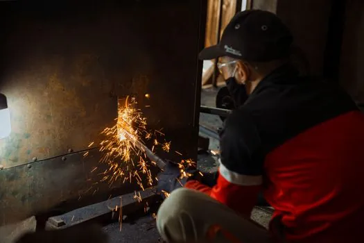
Five actuator and contact-block features are non-negotiable for a welding-cell E-stop: red colour, mushroom head, latching (twist or pull to release), at least one positive-break NC contact, and a fail-safe construction that opens the contact if the actuator is damaged [S5]. Positive breaking means the contact is forced open by a mechanical drive link rather than relying on a spring alone, so a welded contact cannot stay closed during a fault, which is the single most cited failure mode on welding cells [S5][S6].
Typical mounting is 22.5 mm or 30.5 mm panel cut-out on a yellow background, with the actuator height set so an operator wearing MIG/TIG gloves can strike it with a flat palm; palm-height mushroom heads are the default because they can be hit with a forearm or shoulder during a torch-spill event [S3][S5]. The reset must be a deliberate pull or twist, never key-only, because operators need to recover from a nuisance trip without finding a keyholder, and a push-only reset is specifically discouraged by ISO 13850 for that reason [S2].
Contact block ratings have to be sized to the inrush of the welding contactor coil, not just its sealed current; a 6 A resistive rating collapses fast when switching a 40 A contactor coil at 24 V DC, and the usual fix is a contact block rated 10 A resistive / 6 A inductive at the relevant DC voltage, or an interposing relay on the safety output [S6]. See the general selection rules in the emergency stop button reference for the full rating table.
Safety category: PL c minimum, PL d on robot cells
Most welding cells are designed to Performance Level c (PL c) under ISO 13849-1, which can be met with a single-channel E-stop circuit, a monitored contactor, and one normally-closed contact per button, provided the rest of the safety function (contactor, wiring, response time) also holds PL c [S6]. Robot-loaded MIG and spot-welding cells are typically pushed to PL d because of the additional hazard from the robot arm and the servo-driven torch, which requires a dual-channel E-stop wiring with two NC contacts and a monitored contactor pair, or a safety relay/module that cross-checks the channels [S2][S6].
Implementation guidance from 2026-06 specifically documents how to wire an E-stop through contactor auxiliary contacts while holding PL c, using a force-guided (mirror-contact) contactor so a welded main contact is detected through the auxiliary, which is the same pattern used on the welding contactor itself [S6]. A force-guided contactor is the cheapest way to lift a single-channel E-stop from PL c to a recoverable category without adding a second channel, and it is the configuration most builders default to on stand-alone spot welders.
For a fuller comparison against the electrical-work sister cell, the emergency stop selection for electrical work guide lays out the same PL c / PL d logic from the arc-flash side; the wiring topology is identical, only the hazard energy differs.
Integration with welder interlocks, doors, and light curtains
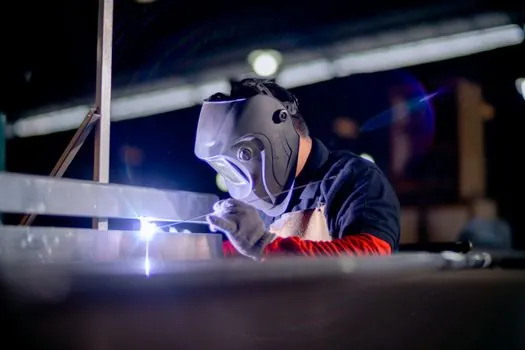
A welding cell E-stop has to be wired into the same safety circuit as the door interlocks, the laser or arc-optical guarding, and any light curtains or safety mats, so a single press drops the entire cell to a safe state in one category-0 or category-1 stop [S2]. ISO 13850 explicitly states the E-stop must be "universal" with those subsystems, meaning it cannot be a stand-alone button only wired to the welding source enable, because a robot motion hazard would still be live [S2].
Welding-specific additions: the gas solenoid (argon, CO2, or fuel gas for flame cutting) must be on the safety output so shielding gas stops flowing when the cell is stopped, otherwise a torch left in a fixture can keep leaking gas into the booth [S1][S4]. A chiller flow switch and a laser source interlock, where fitted, also need to be read by the same safety relay so an E-stop press is recorded as a coordinated cell stop, not a series of independent trips [S1].
Where a light curtain is used at the loading station of a robotic welder, the Safety Light Curtain Selection for Work at Height article documents the resolution and ISO 13855 spacing rules that have to hold in parallel with the E-stop wiring.
Placement rules for welding stations
At least one E-stop has to be within arm's reach of every operator position, including the programming pendant for a robotic welder, the loading side of a fixture, and the gun/trigger side of a manual TIG station, and the rule of thumb used by 2026-era cell builders is one E-stop per 2 m of cell perimeter plus one at every operator station [S3][S5]. ISO 13850 requires the actuator to be accessible without the operator having to reach past a hazard, so on a fixture with a part-loading tray the button sits on the loading side, not the back of the cell.
Fixed-height pedestal E-stops are now common on cells where the operator moves around the fixture, typically a 1.0-1.2 m tall post with a palm button on top and a secondary button at 0.6 m for kneeling or seated work, both wired to the same contact block [S3]. For laser welders and CNC welders with enclosed work envelopes, a second mushroom button has to be mounted outside the enclosure door in addition to any inside it, so a tripped operator can be reached by a colleague without entering the beam path [S2][S3].
Cable-pull E-stops are an option on long weldments, conveyor-fed cells, and large robotic tracks where a single button is impractical, and they are explicitly allowed by ISO 13850 as long as the pull force, the latching, and the positive-break behaviour are equivalent to a mushroom button [S2][S3].
Common failure modes and what to test on commissioning

The top three E-stop failure modes documented in 2026 welding-service bulletins are: contact welding from switching the welding contactor coil directly, mechanical damage to the mushroom head from torch strikes, and reset interlock failures where a button is forced back in before the safety relay has re-armed [S1][S6]. The first is fixed by adding an interposing relay or a contact block with a higher inductive rating, the second by using a slightly recessed head or a metal collar, and the third by training operators to wait for the green reset indicator before pressing the reset [S1][S6].
Commissioning test routine, per the same OEM guidance, runs three checks: (1) press each E-stop and confirm a category-0 or category-1 stop with no arc-flash or gas leak, (2) attempt to restart before reset and confirm the safety relay latches out, (3) attempt a slow reset and confirm the cell only re-energises after a deliberate release-and-confirm action [S1][S2][S6]. A daily check recommended in the troubleshooting flow is a simple "is the E-stop still latched from yesterday" walk-around, because a button left pressed overnight is one of the most common reasons a cell will not start on the morning shift [S1].
For broader emergency-response context, the emergency stop and welding cutting tool reference pages cover the procedural side that pairs with the hardware spec, and the emergency light reference covers the cell-area lighting rule that lets operators find the E-stop in a smoke or fume event.