The five decision drivers — solids passage, TDH, BEP flow coverage, NPSHa margin, and seal material — are not equally weighted; a pump that passes 75 mm solids but runs 30 % to the right of its best-efficiency point will fail faster than a smaller-solids pump run at its design point [S5].
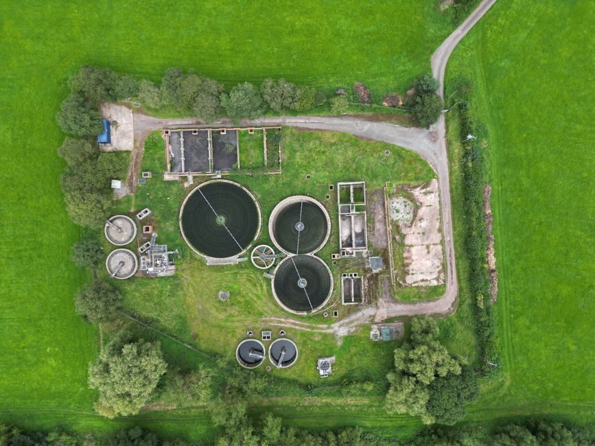
The scope here is the wet-well → force-main lift station typical of municipal and industrial effluent service, where the hydraulic pump sits submerged or in a dry-pit arrangement and must move a variable solids-laden stream against a calculated static + friction head. The envelope below focuses on the selection inputs, not the civil design of the well [S1].
Solids-handling diameter and impeller passage geometry
A wastewater lift station pump must pass the maximum sphere-equivalent particle in the influent, and the public-domain working figure for untreated municipal sewage is a 75 mm (3 in) spherical solids passage for duty pumps, with 100 mm (4 in) specified where ragging is recurrent [S5].
Passage is governed by the impeller eye, the volute tongue, and the gap between cutter bars (on grinder/chopper pumps) — not by the discharge flange size. Selecting a pump purely on flange size is a recurring error on retrofit jobs, because two pumps with the same 100 mm discharge can have 50 mm and 100 mm solids passages respectively.
Total dynamic head, duty point, and BEP placement
Total dynamic head for a lift station is the sum of static lift, friction loss in the force main (Darcy–Weisbach or Hazen–Williams), and minor losses at fittings; the duty point must sit within ±10 % of the manufacturer's published best-efficiency point at the design flow, otherwise efficiency drops and the service interval on the mechanical seal shortens. [S1]
Variable-speed drives shift the operating point along the pump curve rather than throttling it, which is why [S5] reports efficiency gains on variable-speed pumping stations in pressurized irrigation and is now routinely transferred to wastewater force-main duty, where the flow envelope spans roughly 30–110 % of design over a diurnal cycle. A pump that is correctly specified at design but cannot trim below 50 % flow will cycle and overheat the wet-well.
NPSH margin and submergence requirements
The available NPSH at the pump suction must exceed the manufacturer's required NPSHR by at least 0.5 m (1.6 ft) for a clean water service, and by 1.0 m (3.3 ft) when the fluid carries fibrous solids or when the temperature is above 30 °C — values consistent with hydraulic station design guidance for pumping systems [S2].
For a submerged wet-well pump, submergence is set by the manufacturer's anti-vortex bell elevation above the floor, typically 0.5–1.0 × the bell diameter; ignoring this is the most common cause of air ingestion and cavitation on retrofit installations. The pressure transmitter on the discharge side is a poor substitute: by the time suction cavitation shows up as a discharge pressure oscillation, the mechanical seal has already been damaged.
Seal, flush, and material compatibility with wastewater chemistry
Mechanical seals on wastewater pumps are specified as silicon-carbide-vs-silicon-carbide faces with EPDM or Viton elastomers as a baseline; where the stream carries hydrocarbons, solvents, or pH outside 6–9, the seal must be uprated to a plan-32 flush or a cartridge seal with a barrier fluid, and the elastomer must be documented against the chemistry. [S2]
Wet-end materials are typically close-grained cast iron for the casing and 316 stainless for the shaft sleeve; for seawater or high-chloride effluent, super-duplex is moved up the bill. The flow meter on the force main should be specified to read within ±2 % across the operating envelope so that the duty-point check after commissioning is meaningful rather than a guess.
Configuration: submersible versus dry-pit, and clogging-risk rating
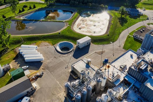
Submersible units dominate new municipal lift stations because the wet-well doubles as the working volume and the motor is air-cooled by the surrounding fluid; dry-pit arrangements remain common in larger (≥200 L/s) stations where accessibility and motor serviceability outweigh the civil cost of a separate dry well. [S3]
A useful comparison frame is the four operating dimensions that most often decide the bid:
1. Solids passage: submersible chopper/grinder 25–50 mm, submersible vortex/channel 75–100 mm, dry-pit end-suction non-clog 75–125 mm, dry-pit axial-flow ≥150 mm.
2. TDH envelope: grinder 5–25 m, vortex 5–40 m, end-suction non-clog 10–60 m, axial-flow 2–15 m.
3. Service interval: grinder every 6–12 months (cutter wear), vortex 12–24 months, end-suction non-clog 18–36 months, axial-flow 24–48 months.
4. Civil cost: grinder lowest (small wet-well), axial-flow highest (large wet-well + dry-pit).
For stations with high rag content, a grinder or chopper pump is selected and a bypass non-clog is held as duty standby; for stations with low rag and high flow, the end-suction non-clog is the workhorse. A PLC running pump-alternation logic and a high-level trip wired through a pressure transmitter on the discharge gives the standard SCADA package most utilities expect.
Limits, failure modes, and what selection cannot fix
No pump selection corrects an undersized wet-well: the working volume must give 6–10 starts per hour at design flow, otherwise even the best-specified pump will trip on motor overload within months. The published literature on hydraulic station efficiency losses [S5] attributes most underperformance to design and operating decisions upstream of the pump itself, not the pump make.
Common failure modes that trace back to selection are: (1) ragging on a non-clog pump that should have been a grinder; (2) cavitation on a pump whose required NPSHR was not checked against the actual submergence at low wet-well level; (3) seal failure from elastomer–chemistry mismatch; (4) bearing failure from running far to the right of BEP. A servo motor is not the answer to any of these — these are pre-specification decisions.
Standards, sourcing, and commissioning checks
The reference documents that govern the specification, not the brand choice, include ISO 5198 for hydraulic pump testing, ISO 9906 for acceptance-grade performance tests, and the hydraulic-system design conventions documented for pumping stations [S1][S5]. Manufacturer product data for replacement-class hydraulic piston pumps and hydraulic stations is publicly catalogued with MOQ and lead-time fields, allowing a quick pre-qualification pass [S4][S2].
The verifiable next node is the pump curve review at the bid meeting; the second is a wet-well drawdown test against the level-instrument calibration sheet before the pumps are handed over.