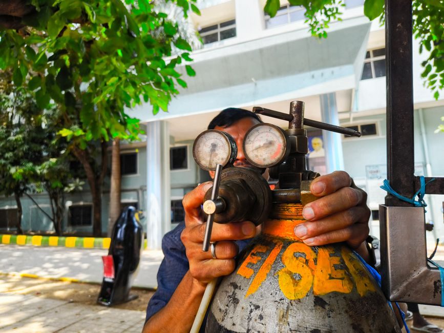
A correctly installed fixed gas detector is a four-part chain — sensor head, field cabling, controller and alarm/relay outputs — and the weakest link is almost always physical placement rather than electronics.
Industrial control units such as the Crowcon Gasflag accept any industry-standard 4-20 mA flammable, toxic or oxygen sensor and expose single-pole change-over relays rated 1 A at 30 V dc, with EMC compliance to EN 50270 and an IP20 enclosure [S1].
Detector Categories, Sensor Targets and Use-Case Fit
Fixed gas detectors split into three functional families: combustible gas (LEL % monitoring for methane, propane, LPG, hydrogen, ethylene), toxic gas (TWA/STEL/IDLH exposure tracking for CO, H₂S, NH₃, Cl₂, SO₂) and VOC/oxygen, and the choice of multi-gas detector versus single-gas instrument is set by whether the working atmosphere is single-component or mixed [S2].
Refineries, pharmaceutical plants and water-treatment sites all produce explosive and/or toxic off-gases that require continuous monitoring, which is why a fixed gas detector architecture — point or open-path — is specified instead of personal monitors [S3].
Combustible gas selection rules from the field: simple single-component atmospheres get a single-gas LEL sensor, mixed-fuel environments (LPG, natural gas, reformer off-gas) require a multi-gas detector so the dominant fuel fraction is correctly identified and explosion risk is bounded [S2].
Mounting Location, Density Rules and Mechanical Layout
Sensor placement is governed by the target gas's relative density versus air, not by convenient cable runs: methane (CH₄) and hydrogen rise and must be sampled near ceiling level, while propane (C₃H₈) and heavier hydrocarbons fall and demand floor-level or low-duct mounting [S2].
Control panel enclosures such as the 210 × 145 × 46 mm, <500 g ABS Gasflag carry an IP20 ingress rating, which means indoor panel-room or cabinet mounting only — outdoor or wash-down locations need a higher-IP field housing [S1].
Forced-air ducts, boiler rooms, swimming pool dosing rooms and garage forecourts are the canonical light-industrial use-cases for LPG, chlorine and methane point detection, and the same sensor-to-controller signal chain is reused with a combustible gas detector head end [S1][S2].
Loop Wiring, Cable Specification and Termination
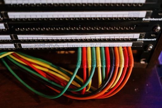
Two-wire or three-wire connection from the sensor head to the control unit runs over screened cable, with terminals accepting conductors from 0.5 mm² to 2.5 mm² cross-section, and the controller is configurable as a 4-20 mA sink or source [S1].
The control unit operates from 13-28 V dc, accepts multiple daisy-chained sensors on the same loop family, and declares a fault current of 23.5 mA as the over-range signature the panel uses to discriminate a real high-gas alarm from a broken cable [S1].
Alarm and fault hysteresis are set at approximately 0.5 mA and 0.2 mA respectively on the controller side, so trip points must be mapped into the 4-20 mA span (e.g. 25% LEL = 8 mA, 60% LEL = 16 mA) and verified with a current source during commissioning [S1].
Controller Outputs, Relay Wiring and Alarm Staging
Single-pole change-over relay contacts rated 1 A at 30 V dc are the standard interface to external audible/visual alarms, solenoid shut-off valves and BMS/SCADA digital inputs, and the panel exposes Alarm 1, Alarm 2, system fault and power-healthy LED channels for at-a-glance status [S1].
Time-to-alarm is specified at less than 1 second from over-threshold to relay action, which is short enough for solenoid shut-off of a gas train but still requires the loop wiring to be screened and routed away from VFD cables to keep EMC within EN 50270 limits [S1].
Multiple Gasflag units can be daisy-chained to cover distributed sites such as a multi-bay garage forecourt or a multi-boiler mechanical room without a separate multiplexer, and the same architecture scales to multi-channel panels such as Gasmaster, GM series or Gasmonitor Plus from the same vendor family [S1].
Calibration, Bump Testing and Functional Verification
Calibration interval is sensor-technology dependent: electrochemical toxic cells (CO, H₂S, NH₃) typically drift faster than infrared point detectors and are bump-tested every 30-90 days, while IR combustible sensors on a gas detector head can extend to 6-12 months between scheduled calibrations [S2][S3].
The bump test sequence is: apply a known concentration of target gas from a calibration cylinder at the sensor head, watch for Alarm 1 trip at the panel within the <1 second response window, and confirm the 4-20 mA loop current matches the expected span value (for example 12 mA at 50% LEL methane) [S1][S2].
Sensor replacement, not recalibration, is required when a cell fails to reach ±10% of the test-gas value after two successive bump tests, and the daisy-chain architecture allows a single failed head to be swapped without taking the rest of the loop offline [S1].
Environmental Limits, IP/IK Rating and Certification Match
Operating temperature for the controller is -20°C to +70°C with storage at -25°C to +65°C, and humidity tolerance is 0-99% RH non-condensing — so the panel side is rugged, but the sensor head's own EX/IECEx zone rating (not the controller's IP20) is what governs whether the detector can sit in a Zone 1 or Zone 2 hazardous area [S1].
EMC compliance to EN 50270 is declared on the controller datasheet; for the sensor head in flammable atmospheres, the installer must separately verify ATEX/IECEx certification matches the zone classification (typically Ex d for Zone 1 point detectors, Ex e for increased-safety wiring) and pull the relevant manufacturer certificate before energising [S1][S3].
Open-path and line-of-sight detector architectures supplement point detection for perimeter monitoring of large process areas, and the open-path gas detector tier map is a useful cross-reference when point coverage is geometrically impractical on a tank farm or process skid [S3].
Acceptance Test, Documentation and Handover Checklist
Commissioning sign-off should record: sensor location and tag number, target gas and alarm setpoints in ppm or %LEL, loop current at clean air (typically 4 mA = zero), loop current at full-scale test gas, time-to-alarm, relay operation at Alarm 1 and Alarm 2, fault simulation (cable break drives 0 mA or 23.5 mA), and EMC verification [S1].
As-built drawings must show cable type (screened), screen earthing point, segregation distance from power cables, daisy-chain node count, and controller-to-BMS address — these are the items most often missing when a maintenance crew returns to the system two years later and cannot trace a nuisance alarm [S1].
Trackable next signals: monitor whether EN 50270 revisions or IEC 60079 series updates land in the next 6-12 months, and watch vendor field notices on electrochemical sensor shelf life for H₂S and NH₃ cells, since those drive the bulk of toxic-gas detector calibration cost in water and waste applications [S1][S3].