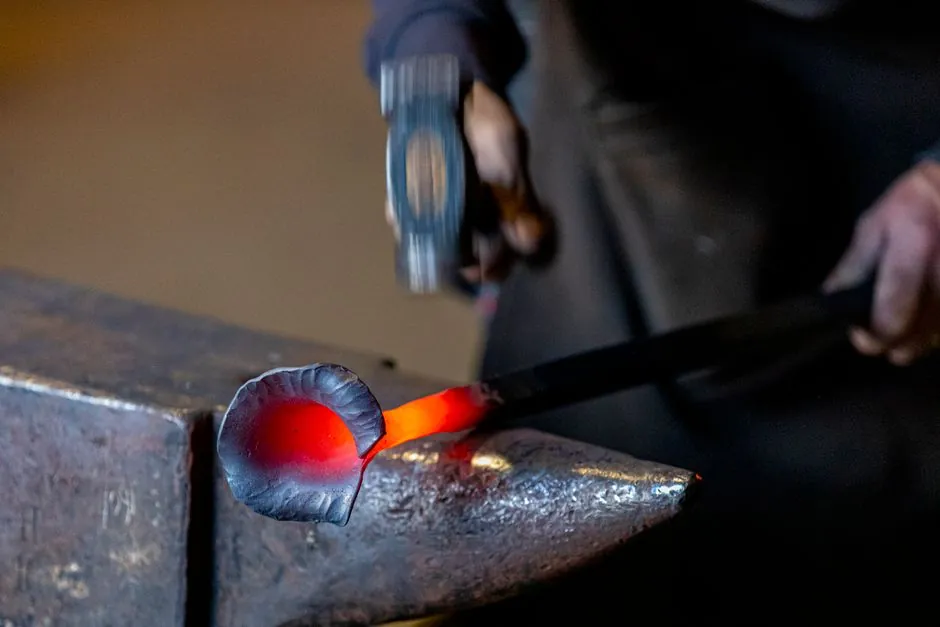
Forged top cups and ledger blades take higher loads in a cuplock system and have more stable quality than pressed-steel equivalents, per current manufacturer guidance [S1]. Pressed cups are cold-formed from a single piece of steel and remain the default for many access scaffolds where peak shoring loads are not present [S2].
The decision comes down to three engineering variables: the cup manufacturing route (forged vs pressed), the parent material grade of the standard (commonly Q235 or Q345 steel tube at 48.3 mm OD, 3.2-4.0 mm wall [S3]), and the cup welding pattern on the vertical (bottom and top cups welded at 500 mm intervals [S3]). For related background on modular scaffolding systems, see the cuplock standard spec reference [S3] and the ringlock-vs-cuplock comparison [S5].
What "forged" and "pressed" actually mean on a cuplock top cup
Pressed cuplock cups are cold-pressed into shape from a single piece of steel with no heating step, which keeps the grain flow of the parent material continuous but limits the geometry to shallow draws [S2]. Forged cups are formed under heat, which refines grain structure and produces a denser, more impact-resistant part that takes more abuse on site before deforming [S1][S2]. The trade-off is unit cost: forging is a multi-step hot die operation while pressing is a single cold stroke, so a pressed cup is cheaper per piece at any volume [S2].
For shoring towers and formwork support where the cup carries repeated vertical drop loads from concrete pours, manufacturer guidance explicitly favours forged top cups and forged ledger blade ends over pressed equivalents, on the basis that the forged part absorbs more energy before cracking and maintains dimensional stability [S1]. On a non-shoring access scaffold (facade, plastering, light maintenance), pressed cups remain acceptable and are the standard fitment on most carbon steel standards [S2][S3].
Cup geometry, weld, and how the load path actually works
A cuplock node is a two-cup assembly welded to a 48.3 mm OD vertical standard: a fixed bottom cup and a movable top cup that is rotated down to clamp the forged blade ends of up to four ledgers in a single node [S3][S4]. Cup spacing on the standard is fixed at 500 mm centres, and the standard itself is supplied in 0.5 m to 3.0 m lengths in Q235 or Q345 carbon steel tube, with 3.2 mm or 4.0 mm wall as the common options [S3]. A 2.0 m standard at 3.25 mm wall weighs roughly 11.82 kg, which is the reference mass for rigging and truck-loading calculations [S3].
The T-shaped forged blade on the ledger end drops into the bottom cup, then the upper movable cup is rotated down over the upper hook of the blade to lock the joint [S3][S6]. Because the top cup transfers the ledger's vertical shear directly into the standard wall through the cup-to-tube weld, the cup base metal and the weld toe are the failure surfaces in overload, not the blade itself. This is why forged top cups (denser grain, fewer defects at the cup throat) outperform pressed cups (possible cold-work thinning at the draw radius) in cyclic drop-load tests reported by manufacturers [S1].
Decision matrix: forged cup vs pressed cup on the same standard
On a Q345 standard at 48.3 mm OD x 4.0 mm wall with 500 mm cup spacing [S3], the practical comparison is:
1. Peak vertical leg load. Forged cup assemblies are specified for shoring and formwork support where the leg sees repeated high vertical drop; pressed cups are kept for access scaffolds with predominantly live and wind loads [S1][S3].
2. Impact and rough-handling tolerance. Forged cups survive hammer blows, dropping off the truck bed, and over-rotation without splitting; pressed cups can crack at the draw radius under the same abuse [S1][S2].
3. Unit cost and lead time. Pressed cups win on both, which is why they remain the default fitment on entry-level cuplock kits [S2].
4. Dimensional consistency. Forged cups hold tolerance better across a production batch, which matters when matching legacy cups to existing standards on a refurbishment contract [S1].
5. Inspection regime. Pressed cups warrant a visual crack check at the draw radius before every major erection; forged cups can be checked by dimension and visual only [S2].
Where pressed cups fail first, and how to specify forged ones correctly
The typical pressed-cup failure is a longitudinal crack at the cup wall, starting at the bottom-radius transition where the steel was thinned by the cold draw, propagating under repeated drop loads from concrete placement [S2]. Forged cups do not have that thinned radius, so crack initiation shifts to the cup-to-standard weld, which is a more predictable and inspectable location [S1].
On the procurement spec, a forged top cup should be called out with: (a) parent material matching the standard (Q235 or Q345 steel), (b) hot-forged cup body with no welded seams in the cup wall, (c) full-penetration fillet weld to the standard, and (d) cup spacing held to 500 mm centres to keep the node geometry consistent with the rest of the system [S3]. The standard reference for the locking action itself is the cup-and-blade mechanism described in cuplock system documentation [S4][S6], and the safety note that manual rotation of the top cup is a known handling step that has to be controlled on site to avoid finger and pinch injuries [S5].
Material grade and interaction with the standard

For a forged cup to deliver its full benefit, the cup parent steel has to be at least as strong as the standard tube, otherwise the weld zone becomes the soft link. The standard cuplock vertical is normally Q235 or Q345 carbon steel tube at 48.3 mm OD [S3], which sets the floor for cup material. Higher-grade options, including alloy steel cups on Q345 standards, are used on heavy shoring towers and are the only configuration rated for the full drop-load envelope cited by shoring-system OEMs [S1][S3].
Surface finish is a secondary but real differentiator: forged cups drop-forged from clean billet show a smoother, more uniform external surface than pressed cups, which often carry tooling witness marks and minor draw lines; that surface finish affects how the top cup rotates on the standard under load, and how easily it can be visually inspected for cracks between shifts [S1].
Selecting for the job, not the catalogue
For a shoring tower or formwork support with repeated concrete-pour drop loads, specify forged top cups and forged ledger blades, with parent steel matched to the Q235/Q345 standard and cup spacing held at 500 mm [S1][S3]. For a light-duty access scaffold on facade work with no dynamic vertical load, pressed cups are fit-for-purpose and give a meaningful cost saving across a large kit [S2].
Track these signals on the next project: the cup marking or stamp on incoming shipments (forged cups are typically maker-stamped, pressed cups are often un-marked), the cup-to-standard weld profile visible at the node, and any crack initiation at the bottom-radius of pressed cups after the first pour cycle. Those three observations will tell you, on the next scaffold strike, whether the cup route on that contract is earning its premium or not. For comparison context on a different shoring-adjacent decision, see the concrete vibration selection map at Flexible Shaft vs Motor-in-Head vs Pneumatic Poker Vibrator and the stud-welding spec map at Drawn arc vs short cycle stud welding.