
A flat face (FF) flange has its gasket surface in the same plane as the bolting face, with no raised step around the bore, so the only gasket shape that fills the entire face and locates on the bolt circle is the full-face type [S1][S3].
On FF flanges in cast iron, fiberglass, or other brittle materials, a full-face gasket is the standard pairing because it spreads bolt load across the whole face and eliminates the bending moment that would crack a thin, brittle flange mating against a raised face [S2][S5].
Geometry: Why FF Has No Step and Why That Forces the Gasket Choice
An FF flange face is in the same plane as the bolting circle face, with the gasket surface extending from the pipe bore out to the flange OD, and because there is no raised sealing ring, the load path from the bolts to the seal is direct rather than concentrated [S1]. ASME B16.5 and B16.47 govern the dimensions of RF, FF, large male/female, tongue-and-groove, and RTJ facings; raised face height for class 150 and 300 is 1/16 in (1.6 mm), and for class 400 and higher it is 1/4 in (6.4 mm), so the FF face sits below that raised reference [S1][S5].
The two flange facings at issue are therefore mechanically different: an RF flange concentrates bolt load on a smaller gasket area to raise pressure containment, while an FF flange distributes load across the full face to avoid bending brittle flanges during torque-up [S2][S5]. RF faces dominate hydrocarbon, chemical, and high-pressure steam service, while FF faces dominate waterworks, fire protection, HVAC, and pump suction piping [S5].
Ring-Type Gasket: What It Seals and Why It Fails on FF
A ring-type gasket has no bolt holes, sits inside the bolt circle around the pipe bore, and on an RF flange rests on the raised surface, so it only needs three dimensions: ID equal to the pipe bore, OD equal to the raised face OD, and thickness [S1][S3]. Ring gaskets are drop-in items; they can be installed without fully disassembling the joint because they do not have to thread around studs, and they use less material and less cutting than a full-face [S1][S3].
On an FF flange, a ring-type gasket has no raised surface to land on, so it relies on the flat face itself for sealing; this is workable for soft, compressible non-metallic sheet on low-pressure FF joints, but it loses the centering benefit of the bolt holes and leaves the outer annulus between the ring OD and the flange OD open to dirt ingress and bolt-side leakage [S1][S4]. A ring-type gasket on FF also tends to be harder to clamp in position because there is no raised face lip to capture it, which is the second mechanical penalty beyond alignment [S3].
Full-Face Gasket: The Standard Pairing for FF
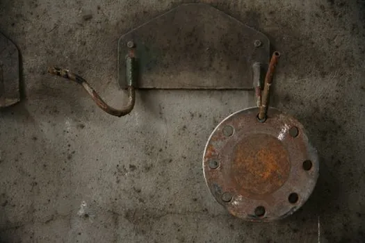
A full-face gasket matches the flange OD exactly, with bolt holes punched on the same bolt circle as the flange, so the gasket covers the entire face from bore to flange OD and is mechanically indexed by the studs [S1][S3][S4]. The required dimensions are ID (pipe bore), OD (flange OD), bolt circle diameter, number of bolt holes, and thickness; bolt circle is measured outer-edge of one hole to inner-edge of the diametrically opposite hole [S1][S3].
That geometry does three jobs on an FF joint: it spreads the seating stress across the whole flange face to protect brittle materials, it fills the gap between the bolting surfaces to keep dirt and wash water out, and it self-centers on the studs so the gasket cannot walk off the bore during torque-up [S1][S3][S6]. The trade-off is that the joint must be fully disassembled to install a full-face because it has to thread over the studs, whereas a ring can be dropped into a partially assembled joint [S1][S3][S4].
Material Pairings by Service
FF flanges are almost always sealed with soft, non-metallic full-face gaskets: EPDM, NBR (Buna-N), FKM/Viton fluoroelastomer, PTFE, flexible graphite, or compressed non-asbestos fiber sheet, because the FF design lacks the seating stress concentration that metallic and semi-metallic gaskets need to bite in [S2][S5][S6]. RF flanges, by contrast, routinely use spiral-wound, double-jacketed, RTJ metal rings, and kammprofile gaskets because the raised face provides the seating stress those designs require [S1][S5].
For a typical FF pump suction or water service line, EPDM or NBR full-face sheet at 1/8 in (3.2 mm) thickness is the default; for chemical compatibility reasons, FF gaskets in chemical duty shift to PTFE, FKM, or flexible graphite, while RF high-pressure hydrocarbon lines shift to spiral-wound with graphite or PTFE filler, and 316L stainless steel winding for elevated temperature [S2][S5][S6]. The compatibility boundary to remember is that metallic and semi-metallic gaskets generally should not be used on a flat face because the face cannot develop the unit load those designs need without deforming the flange [S2].
The Critical Mating Rule: FF Cast Iron to RF Carbon Steel

ASME B31.1 requires that when flat face cast iron flanges are joined to carbon steel flanges, the raised face on the carbon steel flange must be machined off, and a full-face gasket must be used, because the thin cast iron flange would otherwise spring into the gap created by the un-machined RF face and crack during bolt-up [S1]. This is the one hard-coded cross-material rule in the dataset, and it is the reason a full-face gasket is not just preferred but mandated for the most common FF application, which is cast iron to carbon steel transitions in utility and water service [S1].
Broader best practice extends the same logic to any RF-to-FF mating regardless of material: never bolt an RF flange directly to an FF flange, because the RF step will load the FF face on a ring rather than across the full face and reintroduce the bending moment the FF design exists to avoid [S1][S2]. If the system has both flange types in the line, the correct fix is to reface the RF flange flat and use a full-face gasket, not to substitute a ring gasket on the FF side [S1].
Decision Matrix: Which Gasket Goes on Which Face
The decision is driven by face geometry, not by preference, and the matrix lines up cleanly. A full-face gasket on an FF flange gives full-face contact, self-centering on the bolt circle, and dirt exclusion at the cost of full joint disassembly; a ring gasket on an FF flange is sometimes used for low-pressure soft sheet service but loses centering and outer-face sealing; a ring gasket on an RF flange gives a drop-in install and concentrated seating stress at the cost of no outer-face protection; and a full-face on an RF flange is legal but wasteful, since the raised face already concentrates load and the bolt holes add material and cutting cost without a sealing benefit [S1][S3][S4][S8].
For practical specification: choose full-face non-metallic sheet for FF cast iron, fiberglass, or lined flanges; choose ring-type soft sheet only for low-pressure FF joints where bolt-side dirt ingress is not a concern and where the joint cannot be fully disassembled; choose ring-type spiral-wound or RTJ for RF process piping; and never use metallic gaskets on FF without first confirming the seating stress is achievable without flange deformation [S2][S5][S6][S8]. For a worked example of how pressure-class choices on a flanged valve selection propagate downstream, see this Full Bore vs Reduced Bore Ball Valve: Pressure Drop, Cv and Selection reference.
Limits, Failure Modes, and Standards
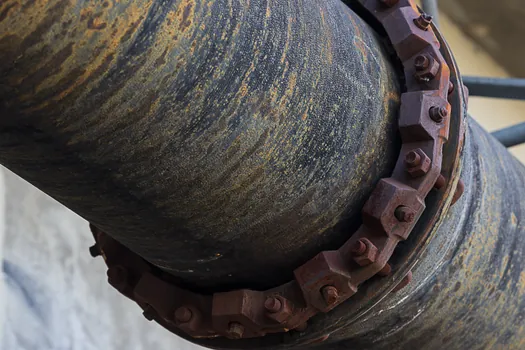
The main failure mode on FF joints is flange bending or cracking at the bore when a non-full-face gasket, or a mismatched RF mating flange, applies a ring-shaped load to a brittle flange [S1][S2]. The second common failure is bolt-side leakage and accelerated bolt corrosion when a ring gasket is used on an FF joint and the outer annulus between ring OD and flange OD is left open to process fluid and atmosphere [S1][S3]. The third is gasket walk or mislocation on FF when no bolt holes are present, which a full-face design eliminates by mechanical indexing on the studs [S1][S3][S4].
The governing standards are ASME B16.5 and B16.47 for flange geometry including FF and RF facings, ASME B31.1 for the cast iron to carbon steel FF-to-RF transition rule, with the 1/16 in (1.6 mm) raised face height for ASME class 150/300 and 1/4 in (6.4 mm) for class 400 and above as the dimensional reference that defines what "flat" means relative to "raised" [S1][S5]. For a deeper background on how flat face flange geometry interacts with gasket selection in a broader sealing spec, cross-reference the retaining ring and O-ring encyclopedia entries when compression-set and squeeze behavior matter.
Trackable next signal: monitor any 2026 update to ASME B16.5 dimension tables for FF facing tolerances, since FF service is moving into higher-pressure lined and FRP piping classes where current FF gasket stress assumptions may need re-derivation.