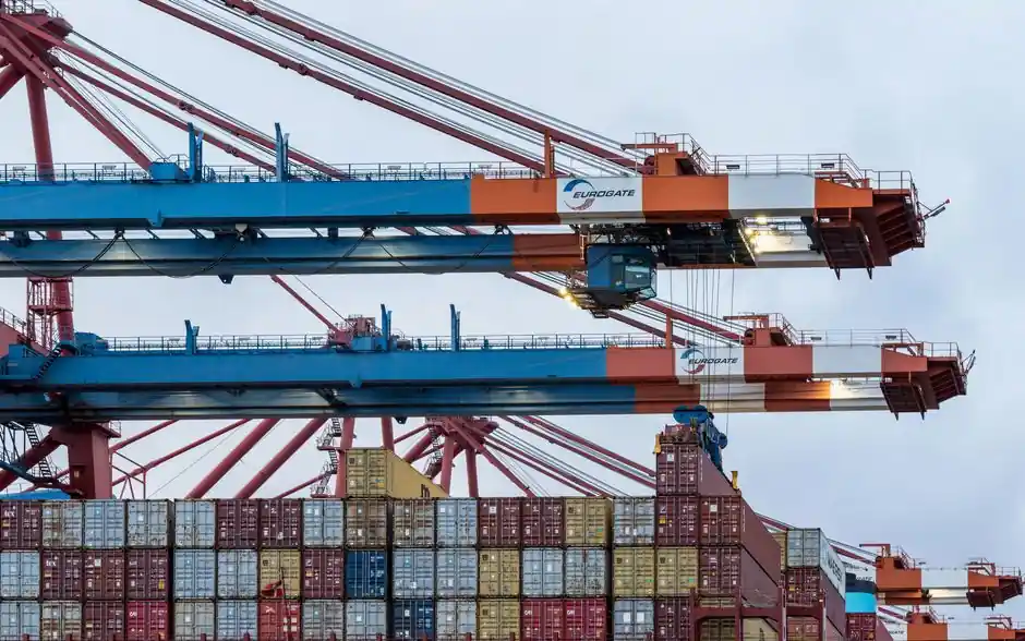
Gantry girders supporting overhead travelling cranes must be designed to resist three orthogonal load families acting simultaneously: vertical wheel loads, lateral (transverse) surge, and longitudinal braking force [S1][S4]. The combination of these actions produces bi-axial bending and torsion, so the rail-level force application forces engineers to treat the top flange as laterally unsupported even on otherwise simple spans [S5].
Selection is governed by lifted capacity, span, crane duty class, and which code family (IS 800/IS 807/IS 875, BS 5950, AISC/ASCE 7, AIST TR-13) applies to the project, with welded plate or box sections replacing rolled I-beams once wheel loads or spans exceed roughly 25–30 t capacity per [S4].
Vertical loads and impact factors
Vertical loads on a gantry girder come from self-weight of the crane bridge, the trolley/crab, the lifted load, and the girder itself, all delivered as concentrated moving wheel loads to the top flange [S2]. The dynamic share of that wheel load is captured by an impact factor, with IS 875 specifying 25% of the maximum static wheel load for electrically operated cranes and 10% for hand-operated cranes as the additional vertical component to add to the static reaction [S5]. For initial design, the same Indian code family also recommends factoring the lifted load (crab weight plus load) for longitudinal and lateral surge at 5% per rail, with hand-operated cranes taking half of those values [S5]. These vertical dynamic shares govern the bending stress check about the strong axis and the shear check at the web.
Lateral surge, transverse force path, and the 10/20/40% rule
Lateral surge is generated by sudden braking of the crab motor (a horizontal thrust at the rail head) and by skewing of the crane while dragging a heavy load across the floor, both delivered as a transverse point load through the main crane wheels into the top flange of the runway girder [S4]. Code-mandated magnitudes diverge sharply: AISC historically required 10% of the lifted load; ASCE/SEI 7-10 (general industry) requires 20% distributed across the bay by lateral stiffness; and AIST Technical Report 13 (steel mill duty) since 1991 has set the lateral load at roughly 40% of the maximum lifted load or wheel load, an order-of-magnitude difference that drives heavier cap channels, horizontal thrust plates, or horizontal trusses back to the columns in mill buildings [S3]. The 2003 revision of AIST TR-13, still unchanged in the 2021 edition, explicitly requires that "the effect of torsional moments and out-of-plane forces at the rail-to-top-flange interface shall be considered", which is the formal recognition that lateral load applied at the rail tip arm produces torsion even on a straight girder [S3]. AIST acknowledges that "an exact analysis and design solution is complex and beyond the scope of this document" and accepts flexural analogy as a satisfactory simplification [S3].
Torsion from eccentric lateral force
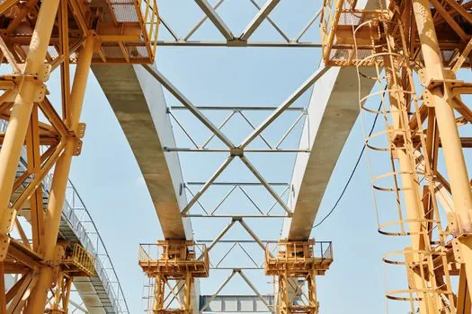
Torsion on a gantry girder is calculated as the lateral load times the depth of the crane rail (the eccentricity between the wheel-rail contact point and the girder's shear centre), and the resulting torsional moment is then distributed to the top and bottom flanges by dividing by the girder depth, the classic flexural-analogy step [S3]. IS 875 simplifies the analysis further by stating that the lateral moment is resisted only by the top flange bending horizontally, with the bottom flange assumed restrained in the vertical plane, so the design bending stress for the lateral component is taken at the full fy/γm0 value [S5]. The IIT-Madras design notes stress that fibre stresses "should rationally be computed considering bi-axial bending combined with torsion" because the vertical-plane moment uses the full girder section while the lateral moment uses only the top flange plus cap channel/cover plate [S5]. This is why cover plates, cap channels, or boxed top-flange details (sections b–f in the IIT-Madras figure set) are routinely adopted: they grow the weak-axis moment of inertia Iyy and the St. Venant plus warping torsion constant J, both of which directly raise lateral-torsional buckling capacity [S5].
Longitudinal loads and load-combination rules
Longitudinal loads arise from acceleration and braking of the crane bridge along the runway and are taken as 5% of the maximum static wheel load under IS 875 for electrically operated cranes [S5]. A critical load-combination rule from IS 875 is that the two horizontal forces (lateral and longitudinal) are not assumed to act together with the vertical load simultaneously; only one horizontal component is combined with the vertical load (including impact) at a time, while vertical load is always present with the impact share [S5]. The design lateral force, however, must be combined with the torsion it induces at the rail-to-flange interface, so the practical combination is vertical + (lateral or longitudinal, whichever governs) + the torsion that comes with the lateral case [S3][S5].
Section selection: rolled I-beam, plate girder, or box

For medium-duty cranes of roughly 25–30 t capacity on short-to-medium spans, a standard universal rolled I-beam is normally adequate, and a cover plate or cap channel on the compression face is added to widen the top flange and improve lateral-buckling strength [S4][S5]. Once spans grow or wheel loads exceed the rolled-section capacity, designers step up to welded plate girders, and for advanced crane systems with high torsional demand, a box girder is preferred because of its inherently high J and bi-axial symmetry, which suppresses lateral-torsional buckling [S2]. For comparison: a rolled I-beam is the lowest-cost option but offers the weakest torsion path; a cap-channel-reinforced I-beam roughly doubles Iyy at modest cost; a welded plate girder scales the web and flanges independently for very heavy wheel loads; a box girder is the top performer for torsion and bi-axial bending but at the highest fabrication cost per metre [S2][S5].
Fatigue, impact, and serviceability checks
Because crane girders experience millions of stress cycles, fatigue is treated as a primary limit state, not an afterthought: design must check the top-flange stress range at the rail-seat location against the relevant fatigue curve, since this is where lateral load and torsion localise the stress field [S4]. Deflection is normally limited to span/600 to span/1000 depending on the code, to keep crane rail alignment and wheel wear under control during the 25-year-plus service life typical of an industrial runway [S2]. The combined check that pulls all of this together is: vertical bending stress (with laterally unsupported compression flange per the rules for unrestrained members) + lateral bending stress in the top flange (at full fy/γm0) + shear from the wheel patch, with each component checked against its own limit and then combined under the chosen load combination [S5]. A useful related reference on wheel-load distribution for runway beams is covered in the gantry crane wheel load calculation guide, and the broader equipment taxonomy sits under construction machinery and equipment.
For a balanced runway design, verify in sequence: (1) factored vertical wheel load plus 25% impact per IS 875, (2) lateral surge at the governing code value (10% AISC, 20% ASCE 7-10, ~40% AIST TR-13), (3) torsion as lateral load times rail depth distributed by flexural analogy, and (4) the compression-flange lateral-torsional buckling check with the section treated as unrestrained between columns. The single highest-leverage failure mode to design against is still rail-to-top-flange torsion on a laterally unsupported span, which is exactly the failure path the 2003 AIST TR-13 update made explicit and that the cap-channel / box-girder detailing directly addresses [S3][S5]. For procurement and layout context, see the single-girder crane family and the broader gantry crane reference on SourceBySpec.