
A portable gantry crane rated 2 tons over an 8 ft (2.44 m) span is commonly built around an 8 in tall x 4 in flange S-type beam at 18.4 lb/ft, with the design driven by stiffness rather than raw strength [S2]. The same physics governs every entry in a gantry load chart: as the span between the A-frame legs widens, the beam section must grow faster than the load, because deflection scales with the cube of the span [S2].
Single-girder gantry cranes in the 1-5 ton class span 7.5-31.5 m with lifting heights of 6-30 m, while double-girder machines stretch that envelope up to 500 t and beyond for shipyard and rail-served applications [S3][S4]. A 20 t mobile gantry, for example, is the practical upper limit of the single-girder family before a structural step-change to twin main girders becomes more economical [S4]. Catalog pages for gantry crane selection typically expose four numbers per model: rated capacity, overall span, maximum cantilever extension A, and the corresponding derated lift B, with required counterweight C on the opposite end of the beam [S1].
How a Gantry Crane Load Chart Is Built
A gantry load chart is a matrix of capacity versus span, derated for cantilever position, with one row per lifting point along the beam [S1]. Engineers derive the entries from finite element analysis on the girder, end carriages, and hoist frame, then apply a safety factor of 3 for standard structures and 5 where personnel are at hazard, with A36 steel assumed for the rolled section [S2]. Dead load, live load, wind load, and dynamic impact are all summed before the safety factor is applied, which is why a beam that is statically strong can still be unacceptable: a crane is designed for stiffness, so a flexible girder that passes a simple strength check will still produce dangerous hook swing and trolley bounce [S2][S4].
For cantilever work, the chart is read differently: capacity B is a falling function of the overhang distance A, because the moment arm on the opposite leg grows linearly with A and the levered load falls roughly in inverse proportion once counterweight C is held fixed [S1]. Manufacturers publish a separate cantilever sheet for each model, broken out by construction material (aluminum, steel, or hybrid), crane family (Tri-Adjustable, Thrifty, Hippolift, Mighty-Mite), and capacity band from 1/4 to 10 ton [S1]. The chart reader's job is to match the load radius, the maximum reach required, and the available counterweight, then read the corresponding derated capacity directly off the table.
Span and Capacity: the Numbers Behind the Curve
Published OEM tables for single-girder gantries show identical span envelopes of 7.5-31.5 m across the 1, 2, 3, and 5 ton ratings, with lifting height 6-30 m on every step [S3]. That span range is wider than most mobile gantries actually need on a job site, but it reflects the modular offering rather than the practical optimum: a 1 ton gantry pushed to 31.5 m would carry a far heavier and more expensive beam than the same 31.5 m crane in the 5 ton class, because the section modulus scales with the bending moment, not the load alone.
For a workshop-grade 8 ft (2.44 m) span at 2 t, the working section lands at an 8 in x 4 in S-beam at 18.4 lb/ft, while a 10 ft (3.05 m) span at the same 2 t typically needs an 8 in deep, 5 in wide, 1/2 in thick section to keep deflection inside the usual L/450 to L/600 span-over-deflection rule used in crane girder design [S2]. The cost driver in that jump is not the steel weight, which only moves a few pounds per foot, but the caster set, since a heavily loaded mobile gantry typically operates on casters sized to roughly 50% of the manufacturer's nominal rating to keep a margin against shock loads from rolling over floor imperfections [S2]. For heavier categories, mobile gantries commonly top out at 15 t before the structure shifts to a rail-served or container-yard configuration, and custom builds can push well past that ceiling when the project justifies it [S5].
Single-Girder vs Double-Girder vs Mobile Configurations
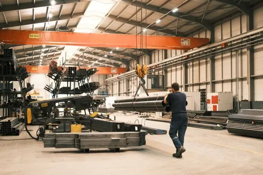
Single-girder gantries are the default for 1-20 t duties, where one main beam carries the hoist trolley on its lower flange and the end trucks ride on the ground or on a rail [S4]. Double-girder gantries take over from roughly 20 t upward and stretch to 500 t and beyond, with the hoist mounted on a trolley that rides on top of the two main girders, which lets the hook hauls closer to the maximum possible headroom and gives the structure a stiffer box-section behaviour under asymmetric loading [S4]. Mobile gantries with rubber tires or casters usually sit in the 1-15 t band because the wheel loads, rather than the girder section, become the binding constraint once the crane is expected to roll under load [S5].
Selection by criteria, with the binding constraint listed first:
1. Capacity and headroom: pick single-girder up to 20 t when headroom is generous; switch to double-girder above 20 t or when maximum hook height is critical [S4].<br>2. Mobility: choose caster- or rubber-tired mobile up to 15 t, rail-served for higher tonnages or repeated cycle duty [S5].<br>3. Span stiffness: target a deflection ratio of L/450 to L/600; at 2 t over 8 ft, an 8 in S-beam at 18.4 lb/ft is the typical fit, while a 10 ft span at the same load needs a heavier flange to keep deflection in check [S2].<br>4. Cantilever duty: read the cantilever sheet line A, B, C together; B falls as A grows, and C is the counterweight the chart requires at the opposite end of the beam [S1].
For site decisions where the crane ties into a permanent structure, the comparison logic overlaps with Free-Standing vs Tied-In Tower Cranes: Structural Support Decision, since both selections hinge on whether the support structure is self-supporting or braced back into the building frame.
Common Capacity Estimation Mistakes on the Job
The single most expensive mistake on a gantry lift is treating the rated capacity as the load limit at full cantilever extension; the chart almost always shows a derated value B that is a fraction of the central-span rating once the load is moved out over the leg [S1][S5]. A second common failure mode is misjudging the load: a piece of machinery that looks manageable on the shop floor frequently arrives with rigging that pushes the gross weight past 90% of the chart value, leaving no margin for the 1.25 dynamic impact factor that the OEM assumes in the rated capacity [S5].
Wheel and floor conditions are a third silent derate. Mobile gantries on uneven ground, soft asphalt, or a floor with a poor sub-base will not deliver the chart capacity, because caster reaction loads concentrate at the high spots and the worst wheel typically carries a disproportionate share of the vertical load [S2][S5]. The matching piece of hardware, the rigging (slings, shackles, spreader bars), must be rated to the same load, since undersized rigging will fail before the beam does and is statistically the more frequent point of failure on a properly sized crane [S5]. Crane-side accessories on a lifting vehicle follow the same logic: the lift chart numbers assume the named accessories, and substituting lighter gear is a common, undocumented derate.
Standards, Materials, and Verification Behind the Chart

OEM charts assume a steel grade (commonly A36 in the North American workshop-crane class) and a defined safety-factor regime of 3 for standard structures, 5 where personnel are at hazard, which is the baseline used in the Practical Machinist sizing thread and matches typical CMAA 70 / CMAA 74 duty classifications for indoor gantries [S2]. Steel gantries support the heavier tonnages, while aluminum gantries trade capacity for portability and are usually limited to the 1/2 to 2 t class, with the chart entries clearly separated by material so the buyer cannot cross-read an aluminum cantilever value into a steel model [S1][S5].
For buyers cross-referencing a construction machinery and equipment catalog, the practical verification step is to ask the vendor for the underlying calculation package: the FEA report, the material certificates, the caster or wheel data sheet, and the published cantilever chart for the specific model number, not the model family [S4]. The published chart is the legal capacity document on most job sites, and a gantry selected by a salesperson's rule-of-thumb rather than the chart is the most common source of an avoidable overload event [S5]. Verification of hoist and trolley performance also depends on a working crane scale reading, since nameplate capacity is only as reliable as the load cell that confirms it on the day of the lift.
The next trackable signals to watch for are vendor releases of updated cantilever sheets for the 2026 model year (Wallace, Better Crane, and equivalent European suppliers typically reissue these when a new aluminum extrusion or hoist family is qualified), and any CMAA or FEM duty-classification revisions that would shift the L/450 to L/600 deflection window for indoor single-girder service. The related heavy-lift market context, including how transformer and turbine moves are stretching the gantry and mobile-crane fleet in 2026, is covered in Breakbulk and Heavy-Lift Capacity Tightens Around Transformers and Turbines in 2026.