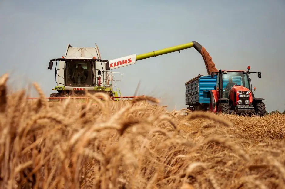
On a tractor PTO, combine harvester, or irrigation pump drive, gear couplings remain the default choice for transferring high torque between misaligned shafts while absorbing shock from tillage, baling, and harvesting loads, per coupling-engineering guidance for heavy and agricultural equipment [S2][S4].
Selection is torque-first: the rated nominal torque of the gear coupling must exceed the application's computed torque, which is the theoretical torque multiplied by an engine coefficient Kw, a working-condition coefficient K, and a start coefficient Kz [S3]. Agriculture drives are typically heavy-impact, dusty, and frequently reversed, which pushes the computed torque well above the steady-state value [S2][S3].
Agricultural Load Profile and Why Gear Couplings Fit
Agricultural drives rarely run at constant load. PTO shafts on tractors are sized for peak torque events during ploughing or baler engagement, and combine harvesters see repetitive shock loads when the cutter bar meets dense crop rows or rocks [S2]. The gear coupling's defining mechanical feature is a pair of meshing external and internal teeth, usually crowned on the internal member, which allows angular, parallel (offset), and axial misalignment while still transmitting high torque with high torsional stiffness [S4][S5].
That combination matters in farm equipment because field machines are mounted on separate frames, with long shaft spans and frames that flex under load, so a rigid coupling would transfer the resulting misalignment into the bearings and seals of the gearbox and implement. A crowned-tooth gear coupling accommodates the misalignment, while the closed-tooth design keeps the dirt and moisture out of the tooth contact better than open spiders or grid springs common in light-duty flexible couplings [S2][S4].
Dust, chaff, and moisture are constant on a farm. Specialized agricultural couplings are explicitly designed to handle dust, shock loads, moisture, and uneven terrain common in farming operations, with seals and lubrication intervals matched to that environment [S2]. For drives that run intermittently (e.g. seasonal irrigation pumps or harvest-time balers), the sealing and grease retention of a gear coupling typically outlast elastomer-insert couplings, which harden and crack under UV and ozone exposure common in outdoor storage [S2][S4].
Step-by-Step Selection: From Horsepower to Coupling Size
The selection sequence used in industry catalogues is: (1) collect base data, (2) compute theoretical and applied torque, (3) apply service factors, (4) pre-select a model, (5) verify bore, speed, and misalignment, and (6) finalize the part marking [S3]. The base data list is fixed: driven machine type, number of prime movers, input power in kW, working speed in r/min, load type, environment, duty cycle, starting frequency, direction reversal, and the input/output shaft diameters and lengths [S3].
Theoretical torque is T = 9550 × Pw / n, with Pw in kW and n in r/min, giving T in N·m [S3]. For a 30 kW motor at 1500 r/min, T = 191 N·m; the catalogue answer is never T itself, it is the computed torque Tc = T × Kw × K × Kz. For heavy-impact agricultural duty on a continuous-duty machine, the product Kw × K × Kz commonly lands between 2.0 and 3.0, which lifts the 30 kW example into a 380-575 N·m selection range [S3][S4].
Special cases then override this baseline [S3]: - High peak load with no reversal: use the system peak torque directly as the selection torque. - High peak load with reversal: multiply system peak torque by 1.5. - Occasional peak load (fewer than 1000 events over coupling life), no reversal: multiply by 0.5. - Brake-equipped drives where brake torque exceeds motor torque: selection torque = brake torque × application factor. - Axial shifting more than 5 times per hour: add 0.25 to the application factor in the computed-torque formula. These rules map directly onto tractor PTO clutching, baler reversals, and seeder row-unit indexing.
Once selection torque is known, the engineer pre-selects a coupling whose nominal torque Tn meets T < Tc ≤ Tn, then checks that the maximum bore covers the larger shaft diameter, that the maximum allowable speed [n] exceeds the running speed, and that the maximum radial dimension fits the shaft-spacing envelope [S3]. Misalignment capability is verified last, because gear couplings tolerate angular misalignment in the 1.5-3.0° per half-coupling range, parallel offset up to a few millimetres, and axial end-float, but the catalogue maximums for angular and parallel misalignment must not be used at the same time [S4][S5].
Service Factors and Misalignment Budgets for Farm Drives
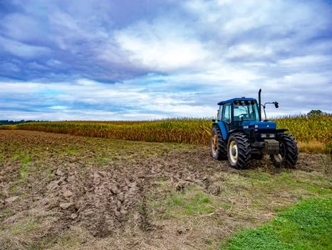
Application factor tables in the major handbooks group agricultural equipment into medium-impact to heavy-impact categories, with a multiplier commonly between 1.5 and 3.0 depending on whether the driven machine is a uniform-load item (auger, fan) or a heavy-shock item (baler, rotary mower, rock picker) [S3][S4]. A tractor-to-PTO-driven implement with a flywheel and shear clutch is usually selected as a shock-load drive, because the shear pin and flywheel mass convert a jamming event into a controlled, but high-magnitude, torque spike [S2].
Misalignment budgets are driven by the implement, not the tractor. A trailed implement with a long drawbar and a single telescoping PTO shaft will see more parallel misalignment at the implement stub than at the tractor output, especially on sidehill operation [S2]. The standard practice is to measure cold and hot alignment with a dial indicator or laser, set the offset within 0.05-0.10 mm per 100 mm of span, and confirm the angular error is inside the gear-coupling maker's plate, typically under 1° per half-coupling for crowned-tooth designs [S4][S5].
For overhung or cardan-shaft drives between tractor and trailed implement, a gear coupling at the gearbox end of the cardan shaft is often paired with a universal joint at the tractor end, so the gear coupling only has to handle the residual angular and axial error after the U-joint has absorbed the gross misalignment. This split is common on large square balers and on self-propelled forage harvesters, where the header driveline sees high parallel offset during lift and float [S2][S4].
Gear Couplings vs Flexible Couplings on the Farm
The decision in farm equipment is usually not "gear coupling or not", but "gear coupling or elastomer/grid coupling at this power level and on this duty". The table below maps the four main options against criteria that matter in agricultural duty, drawn from the Lovejoy handbook and the heavy-machinery selection guide [S4][S5].
- Gear coupling (crowned-tooth): high torque density per bore size, 1.5-3.0° angular misalignment typical, axial float up to several mm, requires periodic grease, IP-classed sealing for dust/moisture, high torsional stiffness (no torsional damping), typical use on tractor PTO, combine header drives, irrigation pump gearboxes, large mixer/feeder gearboxes [S2][S4][S5].
- Elastomer-insert (jaw/spider) coupling: lower torque capacity per size, angular misalignment up to 1° per jaw, electrical isolation, torsional damping for vibration, simple no-lube maintenance, but elastomer hardens under UV/ozone and is vulnerable to chaff ingress; typical use on smaller fans, aeration fans, and light pump drives on grain handling [S4][S5].
- Grid/spring coupling: high torque capacity in a small envelope, good torsional damping, tolerates misalignment similar to gear couplings, the grid element is a wear part and needs replacement at defined intervals; typical use on higher-speed industrial drives rather than open farm machinery [S5].
- Chain coupling: simple, low cost, tolerates misalignment, used on slow-speed heavy-torque drives such as slurry agitators and manure spreader gearboxes; less common in new OEM specifications than gear couplings at the same torque class [S4][S5].
For tractor and combine drivelines above roughly 20 kW and on heavy-impact duty, the gear coupling wins on torque density, sealing, and predictable life, and loses on torsional damping and on the requirement for periodic re-lubrication [S2][S4][S5]. For a low-power aeration fan on a grain bin, an elastomer jaw coupling is usually the better economic and maintenance answer [S4].
Standards, Lubrication, and Failure Modes to Plan For
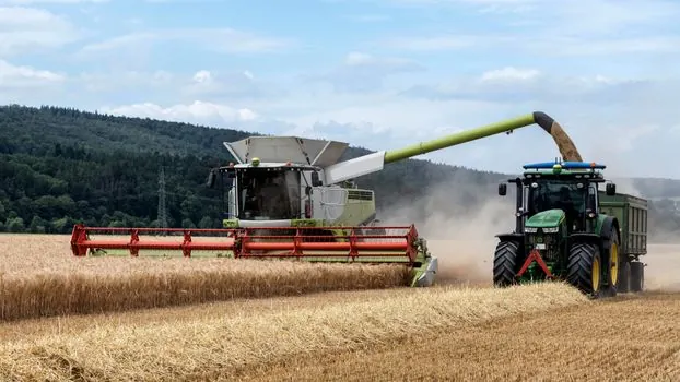
Gear couplings are covered by AGMA, ISO, and national standards (for example, GB/T, JIS, and AGMA 9002 for flexible couplings including gear types), and the manufacturer's published service factor tables are normally aligned with those standards [S3][S4]. The most common in-service failures in agricultural gear couplings are not torque rupture but (1) seal failure leading to grease loss and tooth wear, (2) fretting wear at the spline fit on the shaft from inadequate interference fit or missing key, and (3) fatigue cracking at the hub teeth when the coupling has been run chronically beyond its angular misalignment limit [S2][S4].
Lubrication is the single biggest controllable variable. Standard crowned-tooth gear couplings are grease-filled, and most OEM service intervals on farm equipment call for re-lubrication every 500-1000 operating hours, with the interval shortened in dust-heavy environments such as harvesting in dry conditions [S2][S4]. A greaseless or sealed-for-life gear coupling is available from several manufacturers for shielded installations, at the cost of a lower allowable speed and a more limited misalignment budget [S4].
For PTO drivelines specifically, the guarding, master shield, and the driveline length are governed by ASAE/ISO standards for agricultural tractors and machinery, and those rules sit alongside, not inside, the coupling selection process; a correctly sized gear coupling in an incorrectly guarded driveline is still a safety non-conformance [S2]. The engineer's selection audit should therefore record the computed torque, the service factors applied, the selected coupling's nominal torque, bore, speed, and misalignment ratings, and the lubrication interval, then cross-check the driveline against the relevant tractor/PTO safety standard before release [S3].
Checklist Before Release on a New Agricultural Driveline
1. Record driven machine, prime mover power in kW, running speed in r/min, and direction-reversal frequency [S3]. 2. Compute T = 9550 × Pw / n, then Tc = T × Kw × K × Kz, applying the 1.5× factor if reversal occurs during the peak event, and the +0.25 application-factor bump if axial shifting exceeds 5 events/hour [S3]. 3. Select a coupling whose Tn ≥ Tc, with [T] and [Tmax] both above the maximum event torque including brake torque where fitted [S3]. 4. Confirm bore covers the larger shaft, allowable speed [n] is above the running speed, and the catalogue angular and parallel misalignment limits are not simultaneously maxed out [S3][S4][S5]. 5. Specify grease type, re-lube interval (typically 500-1000 h, shorter in dust), and the sealing class appropriate for the field environment [S2][S4]. 6. Confirm driveline length, guarding, and master shield against the applicable ASAE/ISO agricultural tractor and machinery standard, and document the calculation sheet [S2][S3].
The watch-items for the next 6-12 months are (a) tighter ASAE/ISO driveline-guard enforcement on trailed implements, which is pulling more OEM designs toward fully enclosed gear-coupling shrouds, and (b) growth in sealed-for-life gear couplings on self-propelled machines, where dust ingress and missed greasing are the dominant field failure modes [S2][S4]. For a cross-industry view of the same selection logic on a steel mill drive train, see the steel mill gear coupling selection map, and for an applied walk-through on a clean-in-place food-grade line, see the food processing drives article.
For component-level specifications, see construction machinery and equipment, gear coupling, and gear pump.
This topic is covered further in PPR Pipe Selection for Commercial Buildings: PN, Size, and PP-RCT Rules.