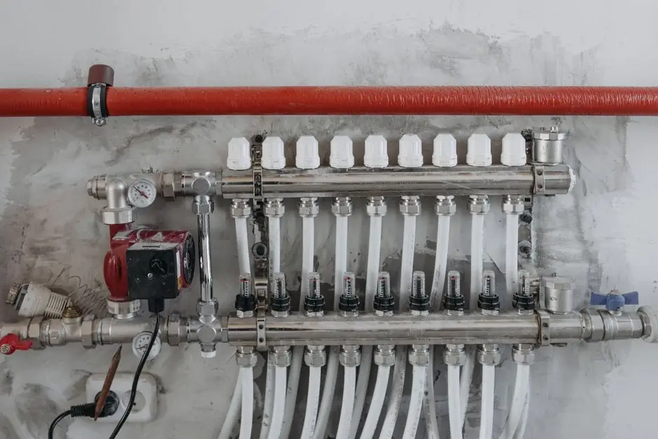
Select an irrigation globe valve whose rated flow covers the design zone demand, whose pressure rating exceeds the maximum working pressure, and whose actuator matches the controller supply.
This guide covers manual, solenoid, buried, and remote globe valves used to divide irrigation systems into controlled zones, with emphasis on flow capacity, pressure loss, filtration, materials, and field maintenance.
Globe Valve Function and Irrigation Duties
A globe valve uses a movable closure element perpendicular to the flow path to start, stop, or throttle water. Its principal advantage in irrigation is accurate flow regulation rather than minimum pressure loss, with standard, angle, Y-pattern, and needle configurations serving different installation and control needs [S4].
In an automated irrigation system, the valve separates the water source into zones so that sprinklers, rotors, drip lines, and planting areas can operate independently. This limits demand on the source while preserving the pressure and flow required by each terminal device [S2]. Separate zones are commonly justified by different emitter requirements, including spray and rotor zones, drip-irrigated beds, and lawn and shrub areas [S2].
Globe valves are suitable where controlled throttling, dependable isolation, and accurate zone flow are more important than the very low pressure loss of a full-port ball valve. They are less suitable as the unrestricted isolation element for a large main line unless the selected variant is specifically rated and sized for that flow [S4]. For broader comparison, ball valve selection for agricultural irrigation addresses full-port isolation and field-failure considerations.
Manual, Solenoid, and Remote Actuator Options
Manual globe valves use a handwheel or handle and need no electrical supply, but they require an operator at the valve and cannot provide controller-based scheduling. The risk of an unattended open valve includes prolonged overwatering and excessive water use [S5].
Solenoid-actuated globe valves normally use a diaphragm, bonnet, and solenoid. With the controller de-energized, inlet pressure holds the diaphragm closed. When the solenoid receives the correct electrical signal, it shifts the plunger, vents bonnet pressure, and allows inlet pressure to lift the diaphragm into the open position [S2][S5].
The actuator must match the controller power source. AC-powered controllers require compatible AC solenoids, while battery-powered controllers require compatible DC solenoids. DC solenoid leads are commonly identified by two different colors, while AC leads normally use two matching conductor colors [S5]. A buried remote valve reduces excavation for field maintenance, but it places access and serviceability directly on the specification.
Buried Globe Valves and Filtered Water
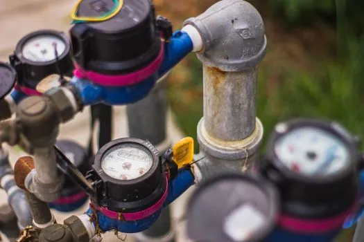
Buried globe valves are commonly installed below ground and are available in a broad range of sizes, which makes them suitable for compact manifolds and remote irrigation zones [S1]. If the valve will be buried, the enclosure, cover depth, access to the solenoid, and local excavation access should be defined before ordering.
Water quality can control the valve construction. Globe valves are commonly used in commercial irrigation systems, where they are installed underground and are available in almost any size [S1]. A separate filter should still be specified because sediment can obstruct a pilot or control passage and impair valve operation [S3].
Do not substitute an angle-seat valve for a globe valve on nameplate pressure alone. The flow path, closure geometry, actuator travel, trim materials, and intended shutoff or throttling duty remain separate selection checks. Likewise, irrigation design should not assume that every valve is suitable for chemical fertilizer, chlorine, sediment, or biological growth without material and seal compatibility data.
Flow and Pressure Selection Criteria
Size the globe valve from the calculated zone flow, not from the pipe diameter or nominal valve size. A valve that is too small restricts available flow, while an oversized valve may fail to open or close reliably at low flow [S3]. The required check is whether the valve's rated flow range contains the minimum and maximum anticipated zone flow.
Calculate pressure at the valve from the source pressure, elevation change, pipe friction, filter loss, sprinkler or emitter requirement, and allowable valve loss. Compare that operating point with the manufacturer's minimum opening pressure, maximum working pressure, and flow-capacity curve. The controller and solenoid voltage must also match the valve nameplate [S3][S5].
Pressure and flow cannot be selected independently. Increasing valve pressure may improve opening force but does not correct an undersized downstream pipe, clogged filter, excessive elevation, or sprinkler demand beyond the zone design. Test the assembled valve under representative operating pressure before installation or field commissioning [S3].
Globe Valve Types Compared for Irrigation
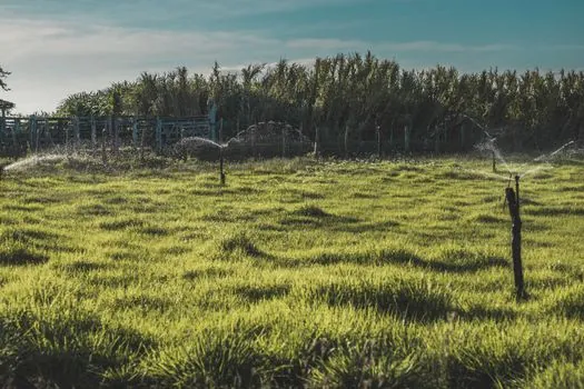
Standard globe valves offer throttling and isolation in a conventional inline body. Angle globe valves change the flow direction through 90 degrees, reducing installation footprint in valve boxes or manifolds. Y-pattern globe valves route flow in a straighter pattern to reduce pressure drop, while needle globe valves provide finer flow adjustment [S4].
For a compact, buried irrigation zone, an angle globe valve with an accessible service box can suit restrictive installation geometry. For a long run or high-flow header where pressure loss must be minimized, a Y-pattern design can be evaluated. A standard globe valve is appropriate when throttling and tight shutoff dominate. A needle globe valve is the specialist choice for fine control, not ordinary full-zone isolation.
Check valves solve a different function: they prevent reverse flow automatically without an external command [S4]. If the irrigation specification requires both manual isolation and backflow prevention, specify separate components or a stop-check assembly. Do not treat a globe valve as an automatic backflow preventer unless its certified construction explicitly provides that function.
Materials, Connections, and Installation Limits
Specify body, wetted trim, stem, disc or diaphragm, seal, and actuator materials against the actual water chemistry and installation environment. Brass construction is common for irrigation control components, while the service requirement determines whether a diaphragm valve, angled valve, or remotely actuated valve is preferable [S5][S7].
Match inlet and outlet connection types to the manifold rather than relying only on nominal size. Confirm female or male thread, socket, flange, or another end connection, as well as valve size, flow range, pressure rating, controller voltage, and solenoid type before release for purchase [S3].
Place filtration, pressure regulation, backflow prevention, and other components where their design pressures and service requirements are satisfied. Filters, regulators, and backflow devices should not be exposed to pressure conditions they were not designed to handle [S2]. Provide straightening, assembly, and maintenance access so the diaphragm, bonnet, solenoid, seals, and filter can be serviced without excavating the entire piping run.
Field Application and Failure Prevention
Commission each globe valve at its intended working pressure and check for full opening, stable flow, complete closure, solenoid response, and leakage around fittings. Weak electrical supply can prevent an automated valve from operating, while sediment can clog a pilot port and restrict control [S3].
Common field failures include a valve that remains closed, a valve that fails to isolate, slow solenoid action, uneven zone pressure, and debris accumulation. Diagnose the valve within the complete assembly: verify controller output and wiring, inspect the filter, confirm available source pressure, check for leaks, and then examine the diaphragm and solenoid. Replacing the valve without checking these conditions may leave the root cause in place [S3][S5].
For automatic backflow control at the system boundary, evaluate an axial-flow check valve or other listed check-valve architecture as a separate selection problem. Its direction, spring behavior, pressure rating, and installation orientation must match the hydraulic design; it does not replace the zone globe valve.
Purchase Shortlist and Verification
A suitable shortlist begins with the zone design flow, maximum and minimum working pressure, water-quality condition, pipe connections, electrical supply, and installation access. Use those six inputs to eliminate valves before comparing trim, diaphragm, seal, and actuator details [S3][S5].
For standard automated zones, request a diaphragm globe valve with a flow range that brackets the calculated demand, a pressure rating above the maximum working pressure, and AC or DC compatibility confirmed against the controller [S2][S5]. For buried restricted spaces, request an angled globe valve with a serviceable cover or valve box and an internal flushing provision where dirty-water service is expected [S1][S5].
Before purchase, require six documented items: rated flow range, maximum working pressure, minimum opening pressure, connection specification, actuator voltage, and material or diaphragm construction. For manual valves, replace actuator voltage with operating effort and access requirements. During commissioning, record inlet pressure, downstream pressure, steady zone flow, and leak status at each valve [S3].