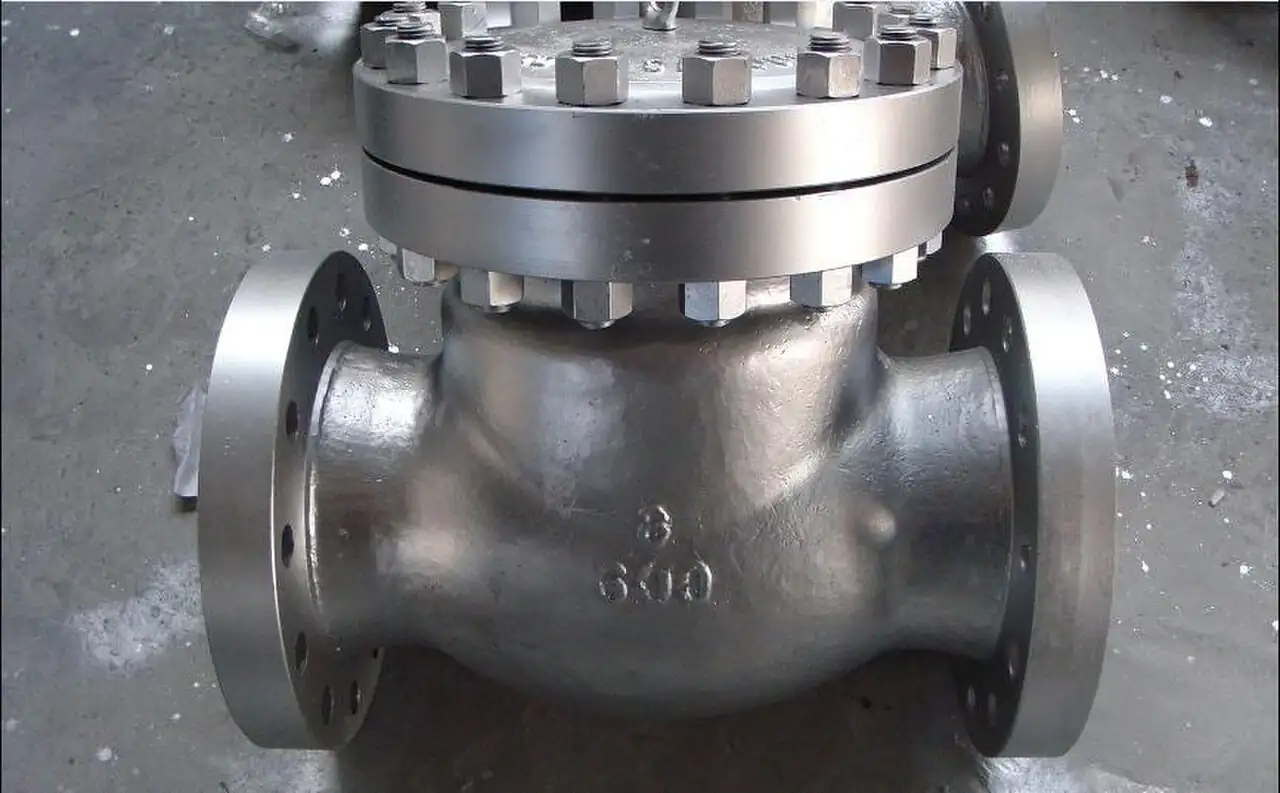
An axial flow check valve is a self acting, spring loaded non return valve in which the disc travels along the pipe axis at the center of a concentric nozzle body. Flow enters, accelerates through an annular passage, lifts a center guided disc against its spring within milliseconds, and passes straight through with no pockets and no protruding hinge; when the pump stops and the liquid column decelerates, the spring and the disc's low inertia start closing immediately, so the disc reseats at or just before the moment forward velocity reaches zero. Closure therefore happens before flow reversal instead of after it, which is what eliminates slam, and the market sells the same concept under the names nozzle check valve and silent check valve. Pressure loss at design flow is typically 2 to 6 kPa, sizes run from DN 50 to DN 600, and pressure classes from CL150 to CL2500.
Procurement engineers meet these valves on centrifugal pump discharge stations in water works, boiler feed and condensate lines, chilled and cooling water banks, and hydrocarbon transfer and loading, wherever a stopped pump must be protected from reverse flow without donating a water hammer event to the piping. The decision this page settles is narrow and practical: whether the station's flow deceleration on pump trip falls inside the valve's dynamic capability, which construction and spring materials match the medium, and what evidence the quotation must carry. The answer lands as an RFQ line set: size, class, laying length, seat and spring materials, leakage acceptance, and the dynamic characteristic curve, and every chapter below feeds that line set so the station is bought against arithmetic rather than habit.
This page treats the axial flow check valve as a purchasing object: how the center guided spring disc closes before flow reversal in real numbers, what dynamic characteristic data says about slam limits at measured decelerations, how much head loss to budget, which spring and seat materials survive the medium, and how all of it combines into a defensible RFQ. It is written for engineers who issue purchase specifications, not for readers who want a brochure summary.
Chapter 1 / 06
What an Axial Flow Check Valve Is and What Is Being Decided
The closure member is the difference. A swing check valve lets a hinged disc ride an arc through the flow stream: it opens lazily, hangs open in the turbulent wake behind the pump, and on trip must fall through a long stroke while the column reverses under it, so it slams. The axial flow design removes the hinge and the arc. Its disc is a short piston guided on a center post by bushings at both ends, seated on the pipe axis, pushed closed by a coil spring and pushed open by the pressure differential across the annular nozzle. The stroke is about one quarter of the seat diameter, the disc reaches full lift within milliseconds of forward flow establishing itself, and because nothing swings out into the stream, the fully open valve is for practical purposes a shaped section of pipe.
What is actually being decided in this purchase is whether the station's worst trip is covered by the valve's measured dynamic capability, and whether the construction details of guide, seat, and spring suit the medium. A check valve is bought for the transient, not for the steady day: on the steady day every type passes flow and shows a loss figure, but on the trip day the swing pattern donates a pressure spike and the axial pattern does not. The buyer commits to a dynamic characteristic, a spring material, a seat construction, and an installation orientation in the same purchase order, and each of those four decisions is checkable against published test data at RFQ stage.
Against its neighbors, the machine occupies deliberate ground, and the working comparison belongs in the selection chapter. The swing check valve remains the answer for solids bearing and raw sewage lines, where its unguided full bore forgives what a guide bushing cannot. The dual plate check valve packs two spring closed plates into a compact API 594 wafer body and covers general water duty at low installed cost. The piston check valve, a spring lifted dashpot style disc in a globe valve body, shares the short stroke principle at smaller sizes and higher pressure classes, and the globe body silent check valve is the same idea from another workshop. The axial flow body takes the territory where all of those compromise: maximum deceleration tolerance, minimum head loss, and any orientation including vertical.
Four standards organize the datasheet. API 594 fixes the face to face dimensions of wafer check valves, which is what lets one maker's wafer drop into another's spool gap. ASME B16.34 governs wall thickness and the pressure temperature rating by class. End flange drilling follows ASME B16.5 in the inch world and EN 1092 in the metric world, and seat tightness is proven at the works per ISO 5208. For context, waterworks swing patterns are standardized in AWWA C508, while axial nozzle designs are built to manufacturer standards inside the ASME B16.34 envelope, which is why the RFQ must pin the dynamic data and the test certificates explicitly rather than lean on a valve standard that covers a different geometry.
The RFQ should also name the whole station, not just the valve. A pump discharge station is a centrifugal pump, suction protection in the form of a Y strainer where debris is credible, the check valve close to the pump discharge, an isolating gate valve or butterfly valve downstream for maintenance, and instrumentation: a pressure transmitter on the header to capture trip transients and switchgear interlocks for reverse rotation. Small branch connections carry their own ball valve for local isolation. Stating the whole station in the RFQ lets one supplier check laying lengths, gasket facing, and class compatibility across the package in a single pass instead of four arguments at commissioning.
Chapter 2 / 06
How the Spring Disc Closes Before Flow Reverses
Mechanically the valve is a spring and a guided mass. Forward flow through the annular nozzle produces a static pressure differential across the disc; once that differential exceeds the spring preload, the disc lifts, and because the stroke is only about 0.25 times the seat diameter, the disc assembly reaches full lift within a few tens of milliseconds. The disc rides on center guide bushings through its entire travel, so it cannot flutter out of alignment or cock in the bore, and the flow path stays concentric with the pipe: no hinge pins in the stream, no disc pocket, and no 90 degree body turn to shed energy into turbulence. The steady state loss is the payoff of that geometry, typically 2 to 6 kPa at design flow, roughly 0.2 to 0.6 m of water.
The transient is where check valves are actually graded. When a pump trips, the liquid column does not stop instantly: it decelerates at a rate set by the system's inertia and head, and laboratory work published by Val-Matic from Utah Water Research Laboratory testing expresses each valve's capability as a dynamic characteristic, the reverse velocity that develops before the disc seats, plotted against column deceleration. The numbers are the reason this page exists. At a deceleration of 9 m/s2, a nozzle style axial valve passes only about 0.06 m/s of reverse flow before seating, a globe style spring centered silent design about 0.10 m/s, a dual plate about 0.18 m/s, a spring flexure swing about 0.55 m/s, and plain swing and ball types more than 0.6 m/s. Field experience grades 0.15 to 0.30 m/s as a mild slam and anything above 0.30 m/s as severe.
Why those decimals matter is one line of arithmetic. Surge pressure from suddenly stopping a reverse column follows the Joukowsky relation in words: the head rise equals the pressure wave speed multiplied by the velocity change, divided by gravity. In steel water pipe the wave speed is about 1000 m/s, so every 0.30 m/s of reverse velocity stopped by a slamming disc produces roughly 30 m of head, about 3 bar, arriving in milliseconds. A nozzle design seating at 0.06 m/s generates a fifth of that or less, which usually disappears into pipe roughness, while a slamming swing disc at 0.6 m/s generates six times more than the mild threshold and hands the bill to gaskets, castings, and pump bearings.
Deceleration itself is computable at desk stage, which is what makes the selection auditable. Divide the pump's design forward velocity by the time the column takes to stop and compare the result with the valve's curve. For example, a column moving at 3 m/s that decelerates over 0.5 s after a trip sees about 6 m/s2; multiple pump high head stations, where one pump's trip is accelerated by its neighbors' headers, reach 12 m/s2 and more. Testing cited by the industry shows single pump low head systems decelerate below about 6 m/s2 while high head multiple pump systems drive past 12 m/s2, and it is exactly in that upper band that spring assisted short stroke valves separate themselves from gravity dependent designs. If the computed deceleration sits above about 6 m/s2, an axial flow design is not a preference, it is the engineering answer.
The worst system response is column separation, and non slam closure is the cheap insurance against it. When the downsurge from a trip or a slam drops the hydraulic grade line below the liquid's vapor pressure, about 2.3 kPa absolute for water at 20 deg C, the liquid flashes open a vapor cavity; when the column rejoins, the cavity collapses and the rejoining surge can exceed the Joukowsky figure. Long pumping mains over changing profiles are the classic territory. The check valve cannot prevent a downsurge caused by the pump trip itself, but by seating before reversal it removes the reverse velocity term that doubles the swing of the transient, and that term is the one the specifier controls for a few hundred dollars at the valve.
Chapter 3 / 06
Types, Construction, and Duty Boundaries
Construction follows one architecture with three variables. The body is either a wafer, built to API 594 face to face dimensions for clamping between pipe flanges, or a full flanged body in ASME B16.5 drilling from CL150 to CL2500; production classes include DFT's PDC style axial nozzle checks, Val-Matic's spring centered silent lines, and, on the spring assisted swing side of the same problem, the Surgebuster concept, which chases the same dynamic characteristic with a different disc. Inside, the flow cage forms the annular nozzle, the disc assembly carries upper and lower guide bushings on a center post, and a coil spring returns it to seat. Standard materials are WCB carbon steel bodies with 316 stainless steel trim for water and utilities, CF8M stainless steel bodies for chemical, coastal, and clean service, and duplex alloys where chloride stress cracking is in play.
The spring is the component that makes the valve non slamming, and it is a specified item, not a catalog footnote. AISI 316 stainless steel springs cover water, condensate, and most chemical duty and are the default. Inconel X-750, a precipitation hardened nickel alloy, is specified for sustained service above 200 deg C and for steam, hot hydrocarbon, and chloride rich streams where standard stainless would relax or pit; a spring that has relaxed quietly converts a non slam valve into a slamming one at the worst possible moment, so the spring line on the datasheet belongs in the RFQ text. Seats are precision metal to metal as standard, with resilient seat inserts, EPDM or PTFE based, available where zero leakage is demanded by the duty or the regulation.
Orientation is largely free, which is a genuine selection advantage. Because closure is spring assisted rather than gravity assisted, the axial design installs horizontally or vertically with flow up; tests indicate spring centered designs actually close slightly faster in vertical lines because disc weight adds to the spring force. Gravity dependent designs behave in the opposite way, which is why a swing pattern that behaves in a horizontal run starts slamming when the same valve is moved to a vertical riser. For deep well and vertical turbine stations this single fact decides the valve type before price enters the conversation.
Duty boundaries are worth stating bluntly. The valve is not an isolation device: it seats well enough to stop a column but not to hold a maintenance permit, so a gate valve or butterfly valve belongs downstream. It is not a solids machine: the center guide clearance that gives the disc its stability packs with fiber and grit in raw sewage and sludge, where a full port swing or a knife gate valve station is the honest specification. And it has a minimum stable flow: below roughly 1.5 m/s sustained velocity the disc can hover part open and flutter, chattering the seat, so minimum flow conditions, not just design flow, belong in the sizing check. Within those boundaries, clean liquid service from minus 20 to 200 deg C and above, water, condensate, hydrocarbons, and chemicals, is exactly its territory.
The duty map below consolidates the boundaries into one table a specifier can scan before writing the RFQ; it pairs common services with the construction that survives them and the construction that generates callbacks.
Service
Suitable construction
Construction to avoid
Clean water pump discharge, municipal stations
CL150 or CL300 wafer to API 594 laying length, resilient seat
Gravity swing patterns on multiple pump high head stations
Boiler feed and condensate
Flanged CF8M body, metal seat, Inconel X-750 spring
Resilient seats and standard springs above 200 deg C
Hydrocarbon transfer and loading
CL300 to CL600, 316 trim, alloy spring, low leakage seat
Undrated wafer installations under thermal cycling
Chilled and cooling water banks
Wafer, resilient seat, standard 316 spring
One size small economies that push velocity and loss upward
Vertical turbine and deep well stations
Spring assisted axial design in the vertical line
Gravity dependent discs in vertical flow
Raw sewage and sludge
Full port swing or knife gate valve stations
Any center guided design in solids bearing flow
Minimum flow and recycle lines
Smaller axial or piston check valve sized at minimum flow
Full size discs that flutter at low velocity
Chapter 4 / 06
Key Specification Parameters
The table below decodes the datasheet lines that decide whether a quoted valve matches the service. Each row is a purchase defining parameter; the paragraphs after the table explain what to demand and what a weak answer looks like.
Attribute
Typical range or options
What it decides
Nominal size
DN 50 to DN 600, larger to order
Wave speed, laying length, and the velocity at which the disc stays stable
Pressure class
CL150 to CL2500 per ASME B16.34
Wall thickness and the pressure temperature table the station lives by
Pressure drop at design flow
2 to 6 kPa, about 0.2 to 0.6 m of water
Lifetime energy cost and NPSH margin at the pump
Disc stroke
About 0.25 x seat diameter
Opening speed and the deceleration the valve can follow
Dynamic characteristic
Reverse velocity vs deceleration curve, tested
Whether the station's computed trip deceleration is covered
Spring material
316 stainless steel standard, Inconel X-750 for heat
Closure authority over the service life in the actual medium
Seat construction
Metal to metal standard, resilient insert optional
Leakage acceptance at the works test per ISO 5208
Orientation
Horizontal or vertical, flow up or horizontal flow
Station layout freedom and closure speed in risers
The dynamic characteristic row deserves its own paragraph because it is the row that separates a specification from a shopping list. Ask for the reverse velocity versus deceleration curve for the exact size and class, from the maker's own test program or from the published laboratory series, and overlay the station's computed trip deceleration on it. A quotation that answers the slam question with adjectives like silent or non slam, but no numbers, is silent exactly where the risk lives. The same paragraph should pin the test basis: works seat and shell testing per ISO 5208, with the leakage rate letter stated, and pressure temperature ratings per ASME B16.34, not per brochure.
The pressure drop row is the money row. Two to 6 kPa at design flow sounds small until it runs 8,000 hours a year through a large header, and the energy arithmetic belongs in the file: on a DN 300 water line at design flow, the difference between 2 and 6 kPa is real kilowatts at the pump, every year, for the life of the station. One size small valves multiply the loss by roughly the square of the velocity ratio and add a flutter risk at part flow. The honest sizing method keeps the line velocity near the design band, checks disc stability at minimum sustained flow, and records both numbers in the RFQ so the supplier owns them.
The type comparison below compresses the geometry decision into the form a specifier can argue from in a meeting.
High head multiple pump stations, boiler feed, vertical risers
Globe style silent
Spring centered disc in a globe body
About 0.10 m/s
Building services and water hammer sensitive loops
Dual plate wafer
Two torsion spring half discs
About 0.18 m/s
Compact general water duty to API 594 laying length
Swing and spring flexure swing
Hinged disc, gravity or spring assisted
0.55 m/s and above
Low head single pumps, solids tolerance, sewage
Piston in globe body
Spring lifted dashpot style disc
Not in the cited test series, short spring stroke keeps it in the silent class
Small high class lines and minimum flow duty
Chapter 5 / 06
Selection Decision Factors and RFQ Language
The decision sequence is short enough to run as a checklist in a specification meeting, and each step eliminates a class of quotations before price comparisons begin.
Compute the station's trip deceleration: design forward velocity divided by column stopping time from the surge study or the pump maker's inertia data.
Compare that number with each candidate's dynamic characteristic curve, and reject any design whose reverse velocity at that deceleration exceeds 0.30 m/s.
Fix the medium and temperature, then the spring: 316 stainless steel for water and condensate, Inconel X-750 above 200 deg C and in aggressive chemistry.
Fix the seat: metal to metal for heat and hydrocarbons, resilient insert where zero leakage is a requirement, not a wish.
Check both flow extremes: pressure drop at design flow and disc stability at minimum sustained flow, roughly 1.5 m/s as the flutter floor.
Confirm the laying length: wafer to API 594 face to face or flanged to ASME B16.5, against the spool drawings.
Name the station context: Y strainer at the pump suction, isolating gate valve or butterfly valve downstream, pressure transmitter on the header for trip baselining.
Fix the evidence: ISO 5208 test certificate with leakage rate, ASME B16.34 pressure temperature table, material certificates, and the dynamic curve in the offer.
Against neighboring valve types, the comparison a specifier actually needs runs as follows, and it belongs here in the selection chapter. The swing check valve wins on solids tolerance, full bore simplicity, and first cost in low head single pump stations, and loses the transient: past about 6 m/s2 deceleration its disc cannot keep up and the slam begins. The dual plate check valve wins on installed compactness and cost in general water duty, at a dynamic capability of roughly a third of the axial design and higher pressure drop. The piston check valve shares the short spring stroke philosophy at small sizes and high classes, in a globe body that costs more pressure drop. The axial flow design wins where the station computes badly: high head, multiple pumps, long mains, vertical risers, and every line where the surge study, not the catalog, picks the valve. Choose the geometry the arithmetic demands, not the type a supplier has on promotion.
The application map below turns that reasoning into a table the project file can carry.
Application
Construction to specify
Check before order
Multiple pump water station, high head
Flanged CL150 or CL300 axial nozzle, metal seat
Computed deceleration against the dynamic curve
Boiler feed water and condensate
CF8M stainless steel trim, Inconel X-750 spring
Seat tightness and spring rating at temperature
Hydrocarbon transfer and loading
CL300 to CL600, metal seat, alloy spring
Spring material against the medium, ISO 5208 rate
HVAC chilled water banks
Wafer to API 594, resilient seat
Laying length against existing spools, gasket facing
Vertical turbine stations
Spring assisted axial in vertical flow
Orientation confirmation and vertical closure data
Pump minimum flow recycle
Reduced size axial or piston design
Disc stability at minimum sustained velocity
The RFQ block should be written once and reused. A complete block reads: quantity, size, and class per ASME B16.34; laying length, wafer per API 594 or flanged per ASME B16.5 with the flange facing stated; medium, density, and operating range with minimum and maximum temperature; design flow and minimum sustained flow with their velocities; computed trip deceleration of the station and the required reverse velocity limit; pressure drop guarantee at design flow, 2 to 6 kPa class; disc stroke and spring material by name, 316 stainless steel or Inconel X-750; seat construction and the leakage acceptance per ISO 5208; orientation of the line; end connections and gasket details; material certificates EN 10204 3.1 for body, disc, and spring; and the dynamic characteristic curve for the offered size as part of the offer, not as a follow up. A quotation returned without the dynamic curve or the spring material is incomplete at any price.
Chapter 6 / 06
Installation, Standards, Failure Modes, and Maintenance
Installation quality decides whether the disc reaches its design life. Place the valve 5 to 10 pipe diameters from the pump discharge nozzle so the distorted velocity profile off the impeller evens out before it meets the disc; a check valve drinking a swirling wake flutters even when correctly sized. Wafer bodies install between flanges with the correct gasket and bolt torque in a cross pattern, never as a spacer under tension; a distorted body binds the center guide and converts a non slam valve into a sticking one. Keep the isolating gate valve or butterfly valve downstream for maintenance lockout, since the check valve is never a permit boundary, and give drain and vent points on the station piping their own small ball valve so the header can be dropped and verified safely. If manual flow regulation is ever attempted in the station, use a globe valve for it; a check valve is not a throttling device, and part flow through a lifted disc is how seats and guides die early.
Commissioning proves two things: that the disc moves and that the transient is what the file promised. At first fill, vent the station fully, because a gas pocket ahead of the disc changes the wave speed and the slam arithmetic. On start, confirm the disc lifts cleanly, usually audible as a soft click rather than a chatter, and record the steady differential across the valve as a baseline for seat wear trending. On a controlled trip test, capture the header transient with a fast pressure transmitter or a chart recorder, and file the trace beside the dynamic curve that justified the purchase; that trace is the station's legal baseline and the maintenance reference for the next decade. Where a Y strainer guards the pump suction, open and clean it after commissioning, since construction debris collected there is debris that never reached the guide bushings.
The standards frame is compact and worth citing by name. API 594 carries the wafer face to face dimensions that guarantee spool interchange. ASME B16.34 carries the pressure temperature envelope and the wall thickness by class. ASME B16.5 or EN 1092 carries the flange drilling, and the gasket facing must be stated with it. ISO 5208 governs the shell and seat test and the leakage rate letters quoted on the certificate. AWWA C508 standardizes the waterworks swing patterns this page's geometry competes against, which is worth citing in the file when a reviewer asks why the axial design is not held to it. Every standard cited in the RFQ transfers the burden of proof to the supplier, which is where it belongs.
Failure modes in service follow a short and predictable list. Spring fatigue or relaxation: closure slows, reverse velocity grows, and the slam the valve was bought to prevent returns quietly; the fix is spring replacement at major outage, and the spring material choice at purchase decides the interval. Guide bushing wear: the disc cocks or drags, showing up as chatter, sticking part open, or refusal to reseat, and in solids service the wear is accelerated by exactly the debris the design was never meant to swallow. Seat wire drawing: continuous small leakage through a damaged seat cuts a groove over months, audible as a hiss on idle pumps and visible as back creep on the header pressure. Debris jamming: a welding ball or a strainer fragment lodged in the guide is the classic commissioning casualty. Each of these announces itself early to a differential pressure trend, which is why the baseline in chapter 2 of the station's life is worth the hour it takes.
Maintenance intervals scale with duty severity more than with cycles. A clean water station deserves a documented trip test and differential reading yearly, an internal inspection at the first major outage after five years, and spring renewal when the measured closing behavior or the transient trace drifts from baseline. Hydrocarbon and high temperature services pull the internal inspection earlier, aligned with the piping integrity program. Solids free operation is the design assumption, so any excursion of debris past the strainer justifies a guide inspection at the next opportunity. None of these checks costs a tenth of one unplanned line stop from a slammed main, and every one of them produces a number the next RFQ can use, which is how a purchasing file gets smarter instead of just older.
FAQ
What makes an axial flow check valve non slamming?
A spring loaded, center guided disc with a very short stroke, about one quarter of the seat diameter, that reaches full lift within milliseconds and begins closing the moment forward flow starts to decelerate. The disc arrives back on its seat at or just before zero velocity, so there is almost no reverse flow to stop abruptly. Water hammer is proportional to the reverse velocity at closure, and that is the variable this design minimizes.
At what flow deceleration will a check valve slam?
It depends on the disc and spring, and the answer is published as a dynamic characteristic: reverse velocity versus column deceleration. Independent tests at the Utah Water Research Laboratory showed that at 9 m/s2 deceleration a nozzle design passes only about 0.06 m/s of reverse flow, a dual plate about 0.18, and plain swing and ball types more than 0.6 m/s. Field experience grades 0.15 to 0.30 m/s as a mild slam and anything above as severe.
Can an axial flow check valve be installed in a vertical pipe?
Yes, and vertical flow up usually improves its behavior. Because closure is spring assisted rather than gravity assisted, orientation is largely free: tests show spring centered designs close even faster in vertical lines because disc weight adds to the spring force. Gravity dependent types behave the opposite way, which is why swing style discs slam more when the same valve is moved to a vertical run. State the pipe orientation in the RFQ so the supplier verifies spring grade.
How much pressure drop should be budgeted for one of these valves?
Plan on 2 to 6 kPa at design flow, roughly 0.2 to 0.6 m of water, for a valve correctly sized to the pipe. The concentric nozzle body has no protruding hinge or disc swinging into the stream, which is why the loss is lower than a fully open swing pattern of the same size. Sizing the valve one size small to save cost multiplies the loss by the square of the velocity ratio and often erodes the seat within months.
Which spring material should be specified?
AISI 316 stainless steel springs cover water, condensate, and most chemical duty and are the catalog default. Specify Inconel X-750, or an equivalent nickel alloy spring, for sustained service above 200 deg C, for steam and hot hydrocarbon lines, and for chloride rich streams where standard stainless would pit and relax. The spring is the component that makes closure non slamming, so a relaxed or corroded spring quietly turns a silent valve into a slamming one.
Are axial flow check valves suitable for sludge and solids bearing lines?
Generally no. The center guide post and its bushings give the disc its stable straight through motion, but solids pack the guide clearance and hang the disc, so the valve sticks partly open and slams or leaks. For raw sewage and sludge, a full port swing pattern or a knife gate valve arrangement is the honest specification. Keep the axial design for clean liquids: water, condensate, hydrocarbons, and chemicals, and protect it with a strainer where debris is credible.
Does an axial check valve need API 594 compliance?
Only its laying length does. API 594 is the wafer check valve dimensional standard, so wafer bodies built to API 594 face to face dimensions drop into the same spool gap as other wafer checks. Pressure integrity and the pressure temperature table come from ASME B16.34 by class, flange drilling from ASME B16.5, and seat tightness is proven at the works per ISO 5208. Cite all four in the RFQ and hold the supplier to certificates, not catalog claims.