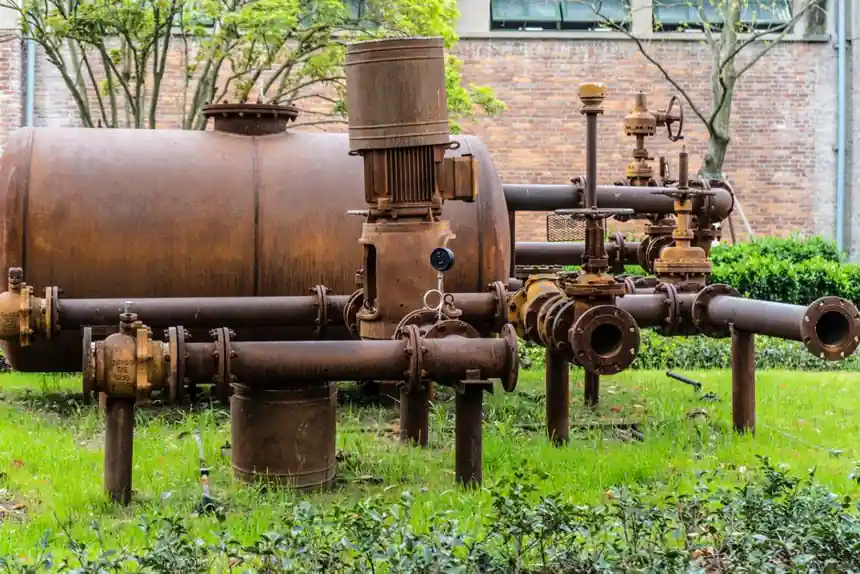
Select an irrigation control valve for stable regulation by matching flow, differential pressure, water quality, and duty cycle to the application.
The practical range extends from simple on-off isolation to automated throttling of wells, ponds, canals, sprinkler zones, and drip-irrigation manifolds.
Separate irrigation valve duties before comparing designs
Irrigation systems use three distinct valve functions: on-off control, flow regulation, and backflow prevention, while additional devices provide pressure relief and air release [S3]. The term “control valve” is therefore too broad for a purchasing specification. A manual gate valve used for zone isolation cannot perform the same job as an actuated globe valve that modulates pressure or flow.
For ordinary on-off service, gate, ball, and plug valves are established choices because their fully open passage provides low pressure loss [S3]. Gate valves use a sliding wedge, ball valves rotate a bored closure member, and plug valves rotate a transverse closure member through a 90° movement [S3]. These designs fit isolation, whereas modulating service requires an actuating mechanism, a stable flow characteristic, and adequate authority through the required operating range [S6].
Buyers should also separate zone control from protection equipment. A backflow preventer prevents reverse flow, an air-release valve removes trapped air, and a pressure-relief valve limits excess pressure [S3][S5]. For a pump or reservoir installation, these devices should be specified independently from the throttling element rather than treated as interchangeable controls.
Use duty and operating frequency to choose the valve family
Valve selection is driven less by extreme pressure capability than by dependable movement of large water volumes through dirty, debris-laden water [S2]. Irrigation water from wells, ponds, and canals may carry sand, silt, scale, algae, fertilizer residue, and organic matter [S2]. Tight internal clearances increase the risk of sticking open, sticking closed, solenoid failure to seat, and check-valve chatter or leakage [S2].
Some valves operate only a few times per season, while others cycle hourly [S2]. Ball valves and purpose-built solenoid valves are more appropriate for frequent operation than isolation-only devices such as conventional gate valves. A gate valve is slow acting because the wedge must move through the full stem travel [S3]. It should not be used for throttling because most shutoff occurs near the closed position, where reduced flow area raises velocity and promotes wedge and seat erosion [S3].
A globe control valve is the default choice when the valve must vary flow continuously. Its internal flow path is suitable for modulation, but it consumes more pressure than a full-bore isolation valve. An angle-seat valve changes the inlet-to-outlet geometry and can suit layouts where straight-through flow is not required [S4]. Solenoid valves suit discrete zone control, while ball valves suit full-port isolation and rapid operation [S4][S5].
Compare the main irrigation valve options by application
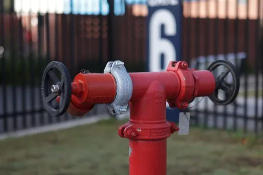
The comparison turns on four criteria: modulation quality, fully open pressure loss, debris tolerance, and operating frequency. Globe and angle-seat designs score where modulation is required; ball and plug designs score where rapid isolation matters; gate valves remain economical for infrequent isolation [S3][S4]. Do not select an ordinary gate or plug valve for regulating a stream: both have nonlinear flow behavior near closure, and partial closure can accelerate internal wear [S3].
Size against required flow and differential pressure
A control valve should be sized to deliver the required flow at the required differential pressure, not simply to match the nominal pipe diameter [S9]. Valve sizing can use a graph relating flow rate, pressure drop, and the valve flow coefficient [S9]. If the available research includes a specific Cv relationship, use it as the procurement criterion; otherwise request the manufacturer’s sizing sheet for the exact fluid and operating conditions.
Three sizing errors have direct field consequences. An undersized valve restricts downstream coverage by creating excessive pressure drop; an oversized control valve can lose useful control sensitivity; and low-flow operation may not provide the force or pressure needed for reliable solenoid operation [S2]. Oversizing is particularly important with globe-style controls because excessive capacity encourages operation near a nearly closed opening, where pressure drop rises sharply and trim behavior becomes less predictable [S3][S9].
For automatic control, define at least four project inputs before requesting a model: design flow in m³/h, upstream and downstream pressure, allowable steady-state pressure loss, and minimum operating flow. Also define the fluid temperature range, maximum operating pressure, required closure duty, allowable leakage, and whether the valve must regulate pressure, flow, or both. A directional-control valve is not a substitute for one of these hydraulic control functions because it routes fluid rather than providing a continuous throttling characteristic [S6].
Match materials and installation conditions to the water
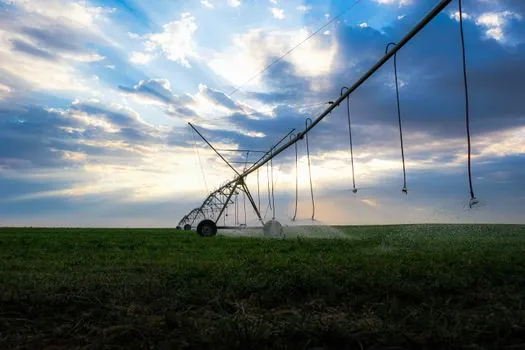
Outdoor irrigation valves face UV exposure, temperature variation, fertilizer and chemical exposure, and water containing sand, silt, algae, or organic debris [S2]. Ductile iron, stainless-steel trim, UV-stabilized PVC, and chemical-resistant elastomers are among the material options identified for agricultural service [S2]. The selected wetted materials must be compatible with the water source, fertilizer concentration, disinfectant, and any injected chemical, not merely with clean water.
Match end connections to the actual pipework. The research identifies threaded BSP, PN16 PVC pressure pipe, and compression-fit irrigation tubing among available connection systems [S5]. Verify the valve port size, thread standard, pressure class, flow direction, and clearance around the actuator before approval. A rising-stem gate valve needs physical space for the stem to rise fully, while non-rising-stem designs reduce that installation envelope [S3].
Actuation and controls form a second package. Electrically efficient valves can support smaller and less costly control wires over longer cable runs [S7]. Specify solenoid voltage and wattage, controller output type, wire size, allowable cable length, and grounding requirements together. Do not select a valve first and force the controls package around it, because a coil that requires excessive power can invalidate the valve’s electrical advantage [S7].
Protect the system with the correct auxiliary valves
Backflow prevention requires a check valve or dedicated backflow-prevention assembly, while an air-release valve removes accumulated air from irrigation piping [S5]. Check valves can chatter or leak when exposed to unsuitable debris or flow conditions [S2]. Their location and orientation must address reverse flow without preventing the intended irrigation sequence.
Pressure relief protects piping and irrigation equipment from excessive pressure, but it does not replace a regulating control valve [S3][S5]. A pressure-relief device normally remains closed until its set pressure is reached, so it has no role in normal zone modulation. Conversely, a modulating globe valve does not guarantee that downstream pressure will remain within the required limit if the pump curve or supply pressure changes.
Common irrigation accessory categories include foot valves, pressure-relief valves, air-release valves, check valves, and solenoid-operated valves [S5]. A foot valve is associated with pump or reservoir suction service, whereas check valves protect against reverse flow. These functions must be identified in the piping and instrumentation diagram so that one valve is not credited with several incompatible duties.
Use an approval sequence that exposes weak selections
Prepare the valve schedule with one row per function, including service, valve type, line size, design flow, design pressure, differential pressure, operating medium, temperature range, connection, actuator, voltage, material, closure rating, and allowable leakage [S6]. Keep isolation, regulation, check, relief, and air-release lines separate. This makes an air-release valve or balancing valve assignment visible instead of leaving it as an unpriced field-added item.
Shortlist globe or angle-seat control only when continuous modulation is required; use ball, gate, or plug valves for on-off service; use solenoid valves for automated discrete zones; and use check, air-release, and pressure-relief devices for their dedicated hydraulic functions [S3][S4][S5]. Reject any submittal that does not state Cv or validated flow capacity at the design differential pressure, pressure and temperature limits, body and trim materials, actuator power, and flow orientation.
Track the installed valve’s actual flow range against the calculated design point, especially after pump replacement or filter changes. A control that passes a workshop bench test can still lose authority if the system operates below its minimum stable flow [S2][S9]. The final commissioning record should verify commanded position, measured downstream pressure, delivered flow, full-open and closed behavior, and leakage against the approved irrigation design.