A correctly sized harmonic filter is selected by four binding numbers — bus voltage, target THID, tuned harmonic order, and step-load response — applied through a Pugh-style decision matrix to choose between passive LC, active IGBT, and hybrid topologies [S5].
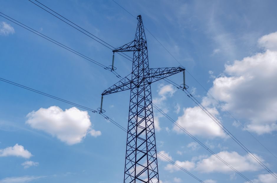
The selection space spans low-voltage (380–480 V) drive panels, medium-voltage industrial feeders, and high-voltage utility busbars; each band demands a different topology, a different current-transformer ratio set, and a different compliance path against IEC 61921 and IEEE 519-2022 distortion limits [S1][S2].
Topology Decision: Passive LC, Active IGBT, or Hybrid
Passive shunt filters are series or parallel LC resonant circuits designed to shunt or block harmonic currents; at the tuned frequency the impedance reaches a minimum equal to the series resistance, after which the branch becomes capacitive and supplies reactive power at the fundamental [S3][S4]. For fixed-frequency loads such as six-pulse rectifiers on MV feeders, single-tuned or double-tuned passive branches are still the lowest-capex option per Mvar absorbed, and they form the backbone of open-rack MV/HV passive filter solutions built around capacitor banks [S2].
Active harmonic filters inject a compensation current equal in magnitude but opposite in phase to the measured distortion; the latest generation of AUNILEC FAFW units responds in less than 300 µs, mitigates odd harmonics up to the 50th order, and limits THID to below 5% on 380–480 V buses drawing 30–100 A at 40 °C [S1]. When the load profile is variable — VFDs, welding rectifiers, dynamic braking — active IGBT units outperform passive banks because they adapt to fluctuating network disturbances without re-tuning.
Spec Gate #1: Bus Voltage, Frequency, and Current Class
LV active filters such as the FAFW cover 380–480 V at 47–63 Hz and 30–100 A rated compensation current, with forced-air cooling and a 1000 m altitude rating, while MV/HV passive filter solutions from Hitachi Energy target medium- and high-voltage capacitor-and-reactor banks where harmonic absorption and reactive support share the same duty [S1][S2]. Mismatched voltage class is the single most common commissioning failure; a 480 V active unit paralleled onto a 690 V drive bus will trip on overvoltage within seconds.
Operating frequency window matters as well: passive LC branches tuned at 50 Hz do not resonate at 60 Hz, so a plant designed for 50 Hz export to North America must re-spec the L and C values, not just relabel. The current-transformer ratio is part of the same gate — AUNILEC specifies external CTs from 100:5 up to 50000:5 to give the controller a clean measurement, and undersizing the CT saturates the FFT analyser and disables the compensation loop [S1].
Spec Gate #2: Harmonic Order Coverage and THID Target

Single-tuned passive branches are optimal when the dominant harmonic order is fixed (typically the 5th at 250/300 Hz), double-tuned branches cover two adjacent orders such as 5th + 7th in one enclosure, and second-order high-pass filters shunt a large percentage of harmonics at and above the tuned frequency with a flat impedance characteristic for the higher spectrum [S3]. For broadband distortion from PWM converters, the C-type high-pass variant reduces fundamental-frequency losses by paralleling L and C across the resistor.
THID post-mitigation is the contractual number to lock. AUNILEC quotes THID < 5% with compensation capability up to the 50th odd harmonic and a compensation response under 300 µs [S1]. IEEE 519-2022 sets the bus-voltage-dependent distortion ceiling at 5% TDD for the most restrictive short-circuit ratio class, so a well-designed active filter usually lands just inside the limit with margin for load growth.
Spec Gate #3: Dynamic Response, Overload, and Paralleling
Dynamic response separates topologies cleanly. Passive LC banks switch in tens of milliseconds via contactors; AUNILEC's active FAFW compensates in less than half a millisecond by analysing network disturbances and providing an opposing compensation current, and absorbs a 2.5×In overload for 10 ms during motor-start transients [S1]. MATLAB's Simscape model confirms that a higher quality factor Q gives sharper filtering but produces high fundamental-frequency dissipation in the resistor — a trade-off the spec writer must call out, not hide [S3].
Parallel operation up to five units lets plant engineers scale compensation as the drive fleet grows without redesigning the bus; this matches the modularity logic used in transformer selection where kVA is added in matching increments. The protective enclosure class is equally binding: IP20 is acceptable inside a sealed LV panel but is rejected on the plant floor, where IP54 or NEMA 3R becomes mandatory.
Selection Matrix: Matching Filter Type to Load Profile

Decision matrices rank a shortlist of options against a fixed set of weighted criteria; criteria go across the top, candidates down the side, and the lowest-entry column usually wins once cost and harmonic-order coverage are weighted [S5]. For harmonic filters, the four most binding criteria are: bus voltage band, load variability (fixed vs VFD), target THID, and step-load response time. Use a cobot-style weight map where each criterion scores 1–5 per topology.
Passive single-tuned LC scores high on capex per Mvar and on reliability for fixed 5th/7th harmonic loads on MV feeders, but scores low on adaptability — re-tuning requires a shutdown [S2][S3]. Active IGBT filters score high on adaptability (odd harmonics up to the 50th order, 47–63 Hz, sub-millisecond response) and on THID < 5%, but require clean CT measurement and forced-air cooling in a controlled enclosure [S1]. Hybrid filter + active trim is the third column; it earns its place when an existing capacitor bank already supplies reactive power and the residual distortion still exceeds IEEE 519-2022 limits.
Who Should NOT Pick the Mainstream Active Filter
Plants with stiff MV utility feeds and fixed six-pulse rectifier loads waste capital on active IGBT units. The reactive-power support, the lower capex per kvar, and the decades-proven reliability of shunt passive LC banks remain the correct duty match, and an active unit on a near-ideal bus simply idles while still requiring cooling, CT maintenance, and firmware updates [S2][S3].
Similarly, a single-tuned LC branch is the wrong answer where the load is a mixed fleet of VFDs, DC drives, and arc furnaces generating a broadband spectrum from the 2nd to the 50th order; a passive branch will only sink one tuned order and leave the rest to circulate. The decision rule is therefore: fixed-order, fixed-load → passive LC; variable-order, variable-load → active IGBT; mixed duty with an existing capacitor bank → hybrid.
Compliance Path and Sourcing Notes
Filter designs should be evaluated against IEC 61921 for power capacitors, IEEE 519-2022 for harmonic distortion limits at the point of common coupling, and the relevant UL/IEC switchgear standard for the enclosure; AUNILEC's FAFW is designed to UL 508 and CE (LVD 2006/95/EC) for the 380–480 V class [S1]. The interface layer is part of compliance: Ethernet, RS-485, and Modbus are the data paths most plant DCS teams already speak, and any filter that does not expose at least one of these will fail the integration review.
For a process engineer building a spec map today, the trackable signals to monitor are: (1) the next IEEE 519 amendment cycle, which may tighten TDD limits on the 5–20 kA short-circuit class, and (2) the growing list of grid codes treating reactive-power support as a contracted service — a path that pushes passive LC banks back into the foreground for utility-scale renewable interconnects [S2]. A spec map written against the four gates above will survive both shifts without rework.
Spec-level background on the components involved: harmonic filter, harmonic reducer, and bag filter.