
A balancing valve is a throttling device with a measurable flow characteristic, installed in hydronic (and process) circuits to set distribution flow to a calculated design value rather than to provide tight shutoff [S1][S3].
Specifying one correctly comes down to four linked decisions: duty type (static manual vs dynamic automatic), body material, port/connection, and a calculated Cv (or Kvs) value backed by a flow-measurement feature such as fixed orifice taps or a multi-turn handwheel with a position indicator.
Duty Type: Manual Static vs Dynamic vs Automatic
Manual static balancing valves are fixed-orifice devices with two pressure taps; the installer reads differential pressure across the orifice, computes flow from the manufacturer-published discharge curve, and locks the handwheel — a low-cost solution for terminal-unit circuits on a constant-volume primary loop [S1].
Dynamic balancing valves combine a regulating element with a differential pressure control cartridge, holding a constant ΔP across the valve regardless of load shifts in the rest of the loop, which suits variable-speed chilled-water plants. For fully variable two-pipe systems, an automatic balancing valve with an integrated pressure-independent control cartridge delivers design flow from 0 to the maximum setting without field commissioning charts.
Across commercial HVAC and light-industrial hydronic work, the manual static variant remains the highest-volume pick because each unit typically lands in the lower end of the price band, while dynamic and automatic types run 2–4× higher per DN size.
Hydraulic Sizing: Cv, Kvs, and Design ΔP
The flow equation ties the published Cv (US gallons per minute at 1 psi drop) or Kvs (m³/h at 1 bar drop) directly to design flow and the allowable pressure drop; under-sizing a circuit by 15–20% of calculated flow is the most common field error and shows up as starved coils and oversized pump head. [S3]
Rule of thumb for terminal balancing: assign 3–5 kPa (roughly 0.5–0.7 psi) of available differential pressure to the balancing valve itself at design flow, leaving the remainder for the coil, pipe, and control valve. This keeps the valve in its readable throttling window — typically a handwheel position between 0.5 and 0.8 of full travel — where the published accuracy of ±5–10% of reading is achievable [S1].
For circuits above DN150 / NPS 6, an ultrasonic clamp-on flow meter can be used for verification instead of the valve's own taps, but the valve body must still carry test ports so the installer can confirm ΔP during commissioning.
Body Material, End Connection, and Pressure Class
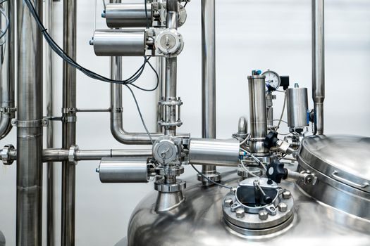
Material choice tracks fluid compatibility and temperature: brass (CW617N / CW602N) bodies in DN15–DN50 for closed-loop HVAC water up to 110 °C; ductile iron (ASTM A536 Grade 65-45-12) with epoxy internal coating in DN50–DN300 for chilled water and condenser water; cast steel (ASTM A216 WCB) for steam, high-temperature hot water, and refinery service.
End connections follow the same logic as the parent piping: threaded BSP/NPT up to DN50, flanged PN16/PN25 or Class 150/Class 300 above that. For systems on 16 bar (PN16) hot-water heating networks with 120 °C supply, ductile iron flanged PN16 remains the workhorse specification.
For differential-pressure measurement to remain accurate, the body should provide two factory-drilled 1/4" NPT or G1/4 pressure-test ports sized to accept a standard piezometer hose, and a memory-stop handwheel so the commissioning setpoint can be reset after isolation.
Comparison: Static vs Dynamic vs Automatic Balancing Valve
Three realistic options, scored against four decision criteria for a 50 m³/h, DN65, PN16, 80 °C condenser-water circuit: (1) Manual static (fixed orifice, two taps): lowest unit cost, no moving cartridge, ±5–10% reading accuracy, not suitable for variable primary flow — best for constant-volume terminal reheat. (2) Dynamic (constant ΔP cartridge): mid-tier price, holds ΔP within roughly ±5% across 30–100% of design flow, no external controller needed, slight head loss even at zero load. (3) Automatic pressure-independent: highest unit cost, delivers design flow to within ±5% from 0–100% load with no field charts, integral control actuator port for BMS trim, slightly larger face-to-face dimension to accommodate the cartridge. [S2]
On a chilled-water plant with variable-speed primary pumps, dynamic valves on each branch plus one automatic pressure-independent valve at the most-loaded coil is a common shortlist that keeps the budget in check while addressing the worst-case index circuit.
Who Should NOT Pick a Manual Static Valve

Manual static balancing valves are the wrong fit on variable primary-flow systems because the fixed orifice cannot compensate for the changing differential pressure produced by a VFD-driven pump — the valve position that balanced the system at 100% flow will be wrong at 50% flow, and the commissioning charts lose meaning once pump speed shifts. [S3]
The same constraint applies to systems with a design ΔP across the balancing valve below 1 kPa (0.15 psi), where the static-orifice measurement accuracy falls off and the installer ends up reading noise. In that operating window, a differential-pressure-measuring valve with a calibrated cartridge is the correct call.
Steam service above 150 °C saturated also rules out brass-body manual units; specify cast steel with stainless trim and metal-to-metal seating, and verify that the body rating matches the saturated steam pressure at the operating temperature.
Use Cases and Application Mapping
Chilled-water plant, DN50–DN150 branch headers: ductile iron PN16 flanged dynamic balancing valve with PN16 flanged body, EPDM seals, and 1/4" NPT test ports; sized for a 3–5 kPa valve ΔP at branch design flow. The same pattern works for condenser water on the cooling-tower side, typically at 32–38 °C with DN65–DN200 bodies. [S3]
Hot-water heating plant, building risers: brass-threaded manual static valve in DN15–DN32, sized for a 2–4 kPa valve ΔP; the small DN15–DN20 body usually lands in the budget-friendly price band and ships with the project's BMS-ready flow-verification log sheet. For AHU-coil branches above DN50, switch to flanged ductile iron.
Process cooling water and light-industrial loops: dynamic balancing valve with stainless-steel trim where the fluid carries particulates or where biocide dosing pushes the corrosion risk up; cast-steel body with stainless trim and graphite gaskets for high-temperature hot water (150–180 °C) and low-pressure steam tracing at ≤1.6 bar saturated. A related resource for adjacent HVAC hardware selection — including broader flow-control component trade-offs — is the encyclopedia entry on control valves.
Limits, Failure Modes, and Sourcing Signals
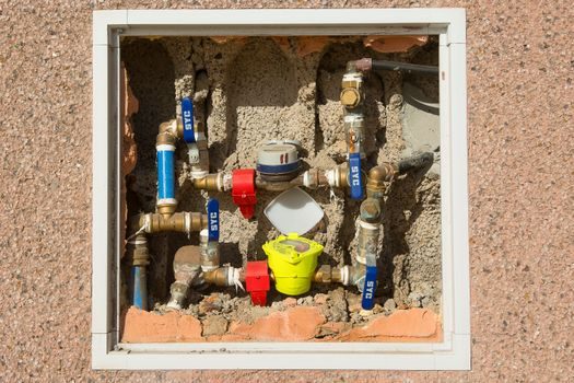
Three failure modes show up repeatedly: (1) operator error from setting the wrong handwheel position on a manual static valve and not recording it; (2) scaling of the test ports on brass bodies in hard-water systems above 60 °C, which kills the pressure-tap accuracy and forces a body replacement; (3) the dynamic cartridge diaphragm aging in constant-ΔP service above 110 °C, which drifts the controlled ΔP upward and starves downstream coils. [S1]
For 2″–6″ (DN50–DN150) flanged PN16 ductile iron PN16 dynamic balancing valves, the project lead time from major Chinese foundry-export hubs has held in a 25–40 day window through the first half of 2026, and stocking distributors in Europe and the Middle East typically carry DN50–DN100 PN16 brass manual static units in 1–2 weeks.
Trackable signals for the next sourcing cycle: published ISO 18534 / EN 12266 leakage-class test reports per shipment, PED 2014/68/EU category I declaration for the DN65 PN16 size class, and the manufacturer's published Cv-versus-turns curve accompanying each valve. A broader comparison of valve types for flow control is a useful cross-reference when a balancing valve is being specified alongside manual isolation valves, and the dynamic balancing machine reference provides background on the related rotating-equipment commissioning term that shares the name.
Related analysis: How to Choose an Aluminum Sheet: Alloy, Temper, Thickness, and Application Map.