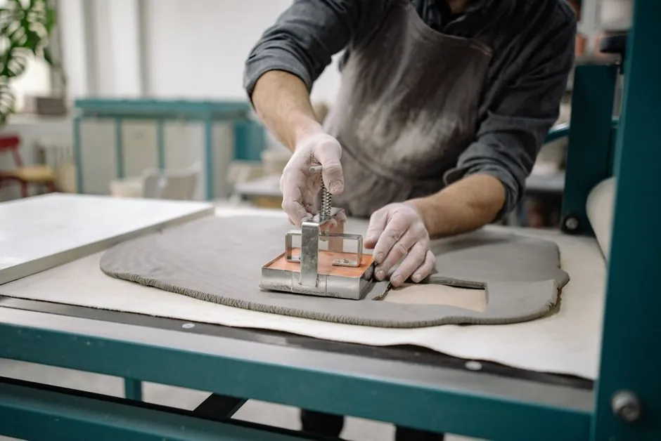
Choosing a casting mold starts with three hard constraints: the alloy or casting medium being poured, the pouring temperature it carries, and the production volume the mold must survive [S2][S3]. Get any of those wrong and the rest of the spec sheet, draft angle, parting line, surface finish, is decoration.
For molten metal work, traditional materials (sand, clay-bonded sand, ceramic, plaster, graphite) still dominate foundries because they tolerate the high melting points of gray iron, ductile iron and aluminum alloys [S3]. For resin, wax, concrete, soap, chocolate and low-temperature casting, the working set collapses to silicone, urethane rubber and HDPE plastic [S1][S2]. A useful first cut is in our casting mold reference, which lays out the same material-vs-process map from a tooling-engineering angle.
Step 1: Lock the Casting Medium and Temperature First
Silicone rubber captures hairline texture, fabric weave and skin-pore detail, and is compatible with resin, wax, plaster, soap, concrete, chocolate and low-temperature metals, but it costs more than urethane and certain grades shrink over time [S1]. Urethane rubber is the abrasion-resistant, low-shrinkage choice for plaster and concrete, including architectural tiles, statuary and stepping stones, and is cheaper than most silicones, but it is not skin-safe and is moisture-sensitive during cure [S1]. HDPE (high-density polyethylene) plastic molds sit between the two: durable, flexible enough to release cleanly, with a slick non-stick surface, and a typical fit for larger projects and reusable craft builds [S2].
For metal, sand molds remain the workhorse because packed sand can be formed around a pattern, withstands the pour temperature of gray iron and aluminum, and is well suited to gravity casting of large, heavy parts [S3]. Clay-bonded and ceramic molds are fired in a kiln before pour, which lets them hold fine detail at the cost of a longer tooling cycle, and they are the default for investment casting where a wax pattern is encapsulated in a ceramic shell [S3]. Graphite sits in a higher-temperature niche, used where the metal or alloy would react with silica-based refractories.
Step 2: Pick the Process Family (Sand vs. Permanent vs. Rubber vs. Plastic)
Sand casting is the default for complex, one-off, or low-to-medium volume iron and steel parts, because the mold is formed around a disposable pattern and replaced each pour; permanent molds (typically cast iron or tool steel) are reused and pay back only when volumes justify the tooling cost [S3][S5]. For non-metal work, the same trade-off shows up as silicone (reusable across many pours) versus alginate (single-shot, skin-safe, used for lifecasts of hands, faces and torsos) [S1]. HDPE is the reusable middle path for craft and small-series resin or concrete work [S2].
A 2026 spec-first approach also requires naming the auxiliary tooling that surrounds the mold: the mold base that registers the cope and drag, the casting auxiliary items (chaplets, chills, risers, vent wire) that control solidification, and the casting ladle sized to the pour weight. For sand work, the sand casting mold reference is the one to keep open, since most of the failure modes in iron foundries trace back to sand compaction, moisture, and binder choice, not the pattern itself. Field experience with shell cores (a related sand-bonded process) is collected in this shell core machine calibration guide, which is directly relevant if your iron or steel line uses shell cores rather than green-sand molds.
Step 3: Match the Mold to the Iron Alloy Family
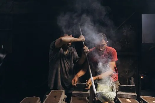
For iron casting, alloy selection drives mold selection, because each alloy has a different carbon equivalent, shrinkage, and cooling demand [S5]. Gray iron, the most widely used casting iron, has excellent castability, machinability and vibration damping, so it tolerates the broadest range of sand systems; ductile iron adds strength, ductility and impact resistance, which tightens the requirement on feeding and risering; white iron is harder and more brittle, so it is reserved for wear parts such as crusher liners and pump bodies; malleable iron is specified where shock resistance and ductility are required, such as agricultural fittings and pipe components [S5].
In practice this means a gray-iron job can run in a green-sand or resin-bonded sand mold with standard draft, while a ductile-iron job typically demands a controlled cooling rate, more generous risering, and often a chemically bonded sand to reduce veining and expansion defects. White-iron wear parts are commonly poured into permanent or semi-permanent metal molds, or into ceramic-shell molds, to extract heat fast enough to lock in the carbide structure. The takeaway: write the alloy grade on the spec sheet before you write the mold material, not after.
Step 4: Spec the Geometry Side: Draft, Parting, Undercut
Silicone and urethane tolerate deep undercuts and complex geometry because they flex, while HDPE releases cleanly on simpler shapes but is less forgiving on long undercuts [S1][S2]. Sand, ceramic and graphite molds require positive draft on every surface parallel to the draw direction, otherwise the casting drags and the mold edge erodes; the typical minimum for sand is on the order of 1.0 to 1.5 degrees, rising with mold depth and surface roughness, though the exact value should come from the foundry's pattern drawing rather than a rule of thumb.
Parting line location is the second geometric decision: it should sit on a non-critical surface, allow a clean draw of both halves, and let the gating system enter through the cope or drag without crossing the parting surface in a way that creates flash. For a 3D-modeled pattern, the standard workflow, as documented in Shapr3D community discussion, is to build two solid bodies (cope and drag) around the model, position a thin parting sheet, and use a Boolean subtract to split the cavity, then verify that no island geometry is left on either side [S4]. The same logic applies regardless of CAD tool: model the cavity halves, model the parting surface, intersect, then subtract.
Step 5: Spec the Process Side: Volume, Lead Time, Cost per Part
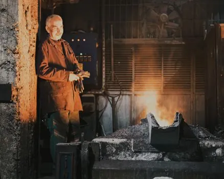
Sand casting is the lowest-cost route for prototypes, short runs and very large parts, because the pattern can be wood or resin and the sand is re-mulled; permanent molds (tool-steel or cast-iron dies) have high upfront tooling cost but the lowest cost per part once volume crosses the breakeven, which on iron is typically reached in the low thousands of parts [S3][S5]. Investment casting (lost-wax, ceramic shell) sits between the two on cost and is reserved for parts that need fine surface finish, thin walls, or complex internal passages, with the ceramic shell molded around a disposable wax pattern [S3].
For craft and prototyping work, silicone is the most expensive mold material but supports many pours per mold and captures the finest detail; urethane rubber is cheaper than most silicones and is the default for plaster and concrete; HDPE plastic molds are reusable and durable but trade off some detail resolution [S1][S2]. The cost-per-part number should be written into the spec sheet next to the expected volume, not derived after the tool is cut.
Who a Sand Mold Is, and Is Not, For
Sand casting is for buyers who need one-off or low-to-medium volume parts, very large parts (engine blocks, pump housings, wind turbine hubs), or parts where the alloy, geometry or lead time rules out a permanent die; it is not for buyers who need tightest dimensional repeatability across tens of thousands of parts, who should look at permanent mold or investment casting instead [S3]. Sand is also the wrong choice when the part has very thin walls, very fine surface finish requirements, or internal passages that cannot be formed by a sand core, all cases where investment casting earns its premium.
Within sand work, a chemically bonded sand system (furan, phenolic-urethane) gives better surface and tighter tolerance than green sand, at higher binder cost and longer cycle; for iron foundries running shell cores, the maintenance discipline that keeps the cores within tolerance is covered in this shell core machine field guide. For surface preparation after casting, the shot blasting machine sizing guide is the practical companion, because the mold choice and the cleaning choice must agree on the surface finish spec.
Decision Matrix: Mold Material vs. Casting Duty
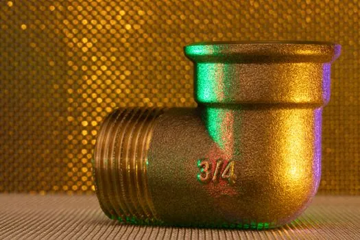
Use this as a working shortlist rather than a final answer: for low-temperature metal (lead, zinc, pewter) and fine detail in a short run, a silicone or silicone-urethane mold is the practical pick; for plaster, concrete and architectural elements in medium runs, urethane rubber offers the best cost-versus-life balance; for iron and steel above ~1,200 C pouring temperature, the choice is between green-sand, chemically bonded sand, ceramic shell or permanent mold, set by alloy, volume and finish demand [S1][S3][S5]. For HDPE plastic molds, the fit is reusable craft and small-series resin, wax or concrete work where detail tolerance is moderate and release properties matter [S2].
Three hard go/no-go checks before signing the pattern drawing: the alloy or medium is named with a standard grade (for irons, ASTM A48 for gray, ASTM A536 for ductile, for example); the pouring temperature and required cooling rate are inside the mold material's published range; and the expected production volume justifies the tooling class. If any of those three is missing, do not cut steel or vulcanize silicone, fix the spec first.
Common Failure Modes and How to Read Them Back to the Mold Choice
Sand casting failures read like a textbook of process variables: veining and penetration point to sand grain size or binder issues; gas porosity points to venting or moisture; scabs and rattails point to mold strength at the mold-metal interface; shrinkage cavities point to riser placement, not the mold material itself [S3]. In silicone, loss of fine detail after a few pours points to tear damage at sharp corners; in urethane, bubble formation and cure inconsistency point to moisture contamination; in HDPE, warping points to pour temperature above the plastic's working limit [S1][S2]. Map each defect to a process variable before blaming the mold material.
For iron specifically, white-iron jobs that come out with the wrong carbide structure almost always trace back to cooling rate, which traces back to the mold's heat-extraction capacity (sand vs. metal mold), not the pattern geometry [S5]. Ductile-iron jobs with porosity or shrinkage almost always trace back to feeding and risering, which is a casting tooling decision, not a mold material decision. The general rule: if the defect is geometric, fix the pattern; if it is metallurgical, fix the process.
Trackable Signals for 2026
Two signals worth watching through the rest of 2026: published revision dates of ASTM A48 (gray iron) and ASTM A536 (ductile iron), which set the alloy grades a foundry quotes against, and the spread of chemically bonded sand systems into short-run iron work, which is replacing green sand on tighter-tolerance jobs. For buyers commissioning a new iron line, the practical next step is to lock the alloy grade, the pouring temperature, and the expected annual volume, then ask the foundry to name the binder system, the draft angle, and the riser layout on the drawing before any tooling is cut. [S5]