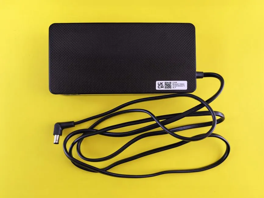
Programmable DC power supplies are specified by maximum voltage, maximum current, and the power envelope they can sustain continuously, with selection driven by the device-under-test, not the catalog headline wattage [S1][S3].
Buyers typically sort the market by output topology (rectangular vs autoranging), control interface (analog, LAN, USB, GPIB), and built-in protection (OVP, OCP), then size the unit with a 10% to 20% margin above the worst-case DUT demand [S1][S3].
Start With the Power Envelope, Not the Wattage Label
The power envelope is the primary specification for any programmable DC supply, and a unit with 10% to 20% excess capacity over the maximum load demand is the standard engineer-side recommendation to absorb startup surges, transient loads, and end-of-life derating [S3]. For example, a DUT that draws 60 V at 5 A (300 W) should be paired with a supply rated for at least 330 W, and 360 W if headroom for future variants is needed [S3]. This margin also compensates for the fact that most rectangular-output supplies cannot deliver full rated current at reduced voltage, a constraint autoranging designs address directly [S3]. A plain bench power supply is fine for one-off bring-up, but any ATE, burn-in, or production test should be built on a programmable unit with documented envelope curves [S4].
Rectangular vs Autoranging Output: Pick the Right Topology
Rectangular output supplies deliver full rated current only at the maximum rated voltage, so usable power collapses as voltage drops; autoranging supplies hold full rated power across a wide voltage window, a critical advantage when DUTs span, for example, 5 V logic and 60 V motor drives on the same bench [S3]. EA Elektro-Automatik autoranging models cited in vendor literature start around 160 W and extend through 480 kW, with full power available down to 33% of rated voltage [S3]. For multi-rail validation work, this single decision often matters more than brand choice, and it pairs well with the broader DC power supply spec discipline. When the load is fixed and known, rectangular supplies are still cost-effective; when the load is variable or future products shift the voltage point, autoranging wins on flexibility per dollar [S3].
Accuracy, Remote Sensing, and Calibration Confidence
Output accuracy is multidimensional: it includes set-point accuracy, load regulation, line regulation, thermal drift, and calibration traceability, and a 4-wire remote-sense connection is the standard way to enforce programmed voltage at the load terminals rather than at the supply binding posts [S3]. For high-confidence calibration, a test instrument ratio of 1:4 (DUT uncertainty to reference standard) is the minimum accepted, with 1:10 preferred in metrology labs [S3]. A supply used for sensor excitation, ADC reference validation, or shunt calibration should always be spec'd with remote sensing and documented ppm/C drift, not just a 0.05% set-point number. As a baseline rule, expect mV-class noise and ripple to dominate measurement uncertainty in sub-24 V precision work, so the ripple spec deserves as much scrutiny as the accuracy number [S2][S3].
Operating Modes: CV, CC, CP, and List/Sequence
Programmable supplies almost always offer constant-voltage (CV) and constant-current (CC) modes, and the higher tier adds constant-power (CP) and arbitrary waveform or list-mode sequencing for battery simulation, solar I-V replay, and accelerated stress tests [S2]. In CP mode the unit continuously recalculates the voltage-current pair to hold a set wattage, which is required for chemistry processes and for emulating fuel-cell or photovoltaic sources [S2]. Overvoltage protection (OVP) and overcurrent protection (OCP) are standard safety primitives, and an auto-cross-over from CV to CC when the user-set current limit is hit is the expected behaviour during battery charging or LED testing [S2]. For engineers building battery cyclers, the transition logic between CC and CV matters more than headline accuracy, and it is one of the reasons a bench DC power supply is rarely sufficient for production test.
Interfaces, Automation, and Waveform Generation
Remote control is no longer optional: standard interfaces include USB, LAN (LXI), RS-232, and GPIB on legacy ATE, with SCPI as the dominant command set and IVI drivers available for most languages [S1][S5]. Some programmable DC supplies integrate a function generator internally, which removes the need for an external source when simulating transients, inrush, or automotive load-dump profiles, and also avoids the safety mismatch of feeding a low-power signal into a high-power output stage [S3]. For bench users, look for a clear front panel with rotary encoders, sense terminals, and a clear OVP/OCP set entry; for rack integration, prioritize LXI LAN, hardware interlock, and analog programming inputs [S1][S5]. A related bench tool, the function generator, is covered separately for HVAC and instrumentation work, and bench pairing guidance is detailed in this function generator selection piece.
Power Input, Form Factor, and Thermal Reality
For most supplies above 1,500 W or 1,500 VA, a 120 VAC wall outlet is no longer sufficient, and 220 VAC single-phase, 208 VAC three-phase, or 400 VAC three-phase feeds become mandatory, with the exact input driven by site infrastructure and total rack load [S4]. Form factor flows from this: small bench units up to a few hundred watts are convection or fan-cooled and sit on the bench; above 1 kW the unit typically moves to a rack or floor-standing chassis with forced-air cooling; liquid-cooled or regenerative cabinets appear above 10 kW in ATE and battery-cycling labs [S2][S4]. Buyers routinely under-spec the AC input side, then discover the supply trips on inrush, so check inrush current, harmonic distortion (THDi), and the available breaker headroom before signing the PO [S4]. Industrial buyers also need to confirm the switching power supply topology inside, since linear vs switching dictates weight, efficiency, and ripple by orders of magnitude.
Application Match-Up: Where Each Variant Fits
R&D and design-validation benches usually want autoranging output, list-mode sequencing, and LAN/USB control in a 1 kW-class chassis, since engineers iterate on DUTs across voltage and current points [S1][S3]. Manufacturing ATE and burn-in racks benefit from rectangular-output supplies sized tightly to the DUT, because the load profile is fixed and the throughput cost of over-sizing is real; bidirectional or regenerative units apply when the DUT is a battery or motor returning energy to the grid [S4]. Compliance and safety labs prioritize calibration traceability, low ripple, and 4-wire sensing, and they will pay for a metrology-grade unit with published ppm/C drift curves [S3]. Field service and embedded work, by contrast, can be done with a 100 W to 300 W portable programmable power supply with USB control and battery operation, where size and weight dominate the spec.
Limitations, Failure Modes, and Who Should Not Pick the Mainstream Choice
Do not pick a generic rectangular-output supply when the DUT pulls peak current at low voltage, because the supply will current-limit prematurely and the test result will be wrong, not just slow [S3]. Do not pick a switching supply for low-noise analog work, where a linear or linear-after-regulator architecture is mandatory; switching residuals at 100 kHz to 1 MHz couple into sensitive measurement paths even with remote sense [S2]. Do not pick a single-quote bench unit for unattended burn-in: missing hardware interlock, missing OVP latch, and missing watchdog timer are common production-failure causes, and they are not visible in headline spec sheets [S1][S5]. If the load is a battery, a PV array, or a bidirectional inverter, a standard programmable DC supply is the wrong tool and a regenerative bidirectional source is the correct one, regardless of brand.
Selection Checklist and Trackable Signals
A defensible shortlist requires five items in writing: (1) max V, max I, and the V/I operating point the DUT actually sits at; (2) 10% to 20% envelope margin documented; (3) load regulation, line regulation, and ripple numbers with units; (4) OVP, OCP, OTP set ranges and latch behaviour; (5) interface list (USB, LAN/LXI, GPIB) and SCPI command reference version [S1][S3][S5]. On the supply-chain side, track Q3 2026 lead times on 1 kW to 5 kW autoranging chassis and watch for new product launches on the EA Elektro-Automatik 480 kW upper boundary, since both are the kind of lead-time and roadmap signals that change a buying decision [S3][S4]. For power-electronics bench work that goes beyond DC sourcing, the IGBT reference on bill of materials and the power semiconductor supply chain walk-through give the surrounding context a buyer will need.