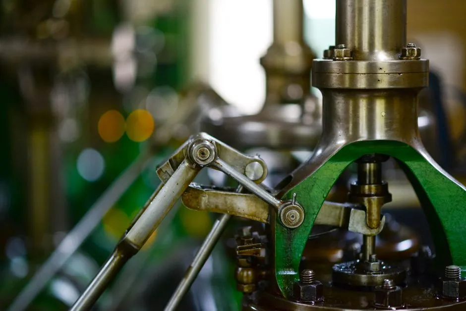
A diaphragm valve body is defined by the shape cast into the flow path: a raised saddle (weir) the diaphragm seals against, or a flat, straight-through bore the diaphragm lifts clear of [S1][S2]. Both arrangements keep all moving parts behind a flexible elastomer or PTFE membrane, which is why diaphragm valves dominate hygienic, corrosive, and abrasive services across chemical, pharma, food, water, and mining lines [S1][S7].
The two patterns share the same bonnet, compressor, and diaphragm assembly; what changes is the flow geometry, the stroke the diaphragm must travel, the achievable shutoff class, and the maximum solids the line can carry [S1][S5]. Treating "diaphragm valve" as a single product hides a real engineering split that affects pressure rating, throttling accuracy, and maintenance intervals.
Weir Pattern: Saddle Geometry and Where It Wins
Weir-pattern bodies contain a raised ridge across the bore, so the diaphragm only has to travel a short distance before the membrane compresses against that saddle to form a leak-tight seal [S2][S3]. That short stroke cuts flex stress on the diaphragm, lets manufacturers run higher pressure classes, and allows a wider choice of diaphragm compounds including PTFE for aggressive chemicals [S2][S5].
Because the saddle sits in the flow path, a weir valve is a throttling device first: clean fluids, clear chemicals, and low-solids services are its strong suit, and the same body can act as both isolation and control valve on a single line [S1][S4]. Body options (plastic-lined, rubber-lined, glass/PTFE-lined, or solid metal) let the same geometry handle acids, caustics, and sterile process streams without changing the actuation package [S2][S5]. A diaphragm valve built on a weir body is usually the first pick for chemical dosing, clean utility, and sanitary CIP loops where tight shutoff matters more than minimum pressure drop.
Straight-Through Pattern: Full Bore and Solids Handling
Straight-through (also called full-bore or straight-way) bodies have a flat floor with no internal ridge, so the diaphragm lifts clear of an unobstructed circular passage equal in size to the connecting pipe [S1][S3]. Flow coefficient Cv runs close to that of an equivalent pipe section, and the valve will still seal when the line carries sand, fibers, crystals, or high-viscosity slurries that would pack up against a weir saddle [S2][S4].
The trade-off is a longer diaphragm stroke, higher flex strain per cycle, and a lower published pressure rating than a same-size weir body [S1][S2]. Straight-through patterns are common in mining slurry lines, pulp and paper stock, wastewater, and pigment or resin transfer, where anything that hangs up on a saddle will eventually cut the diaphragm [S4][S5]. Compared with a ball valve on the same line, the straight-through diaphragm keeps the wetted path rubber- or PTFE-lined, which is why it is often chosen over metal seated alternatives on abrasive service despite the higher pressure drop of a partially open ball.
Decision Matrix: Weir vs Straight-Through on Four Criteria

Process engineers normally pick between the two body patterns on four criteria: shutoff class, solids tolerance, pressure rating, and throttling accuracy. The matrix below is consistent across manufacturer literature and is the basis most EPC specs use to lock in a pattern before materials are picked [S1][S2][S5].
Weir pattern: higher operating pressure class for a given DN, tighter shutoff on clean fluids, better throttling characteristic (approximate equal-percentage-like curve), limited tolerance for entrapped solids. Straight-through pattern: lower pressure class on the same size, full-bore Cv close to the line, robust shutoff with sand, fibers, or crystals present, weaker as a throttling device because the long diaphragm stroke gives a less repeatable characteristic [S1][S2][S5]. When the spec calls for modulating control, pick weir; when the spec calls for slurry isolation, drain, or tank-bottom service, pick straight-through.
Body and Diaphragm Material Selection by Service
Body material is independent of pattern, but it usually pushes the decision one way or the other. Solid stainless (316L) or alloy bodies suit clean chemical and pharmaceutical duty, while rubber-lined (EPDM, natural rubber, butyl) or PTFE/PFA-lined cast iron or carbon steel bodies are standard for acids, caustics, and abrasive slurries [S2][S5][S7]. Sanitary builds add electro-polished 316L bodies and ASME BPE-style end connections, which both patterns can accept because the bore and weir are machined or cast to the same hygienic surface finish.
Diaphragm compound then has to be compatible with both the process and the chosen body: EPDM for steam, hot water, and many alkalis; FKM (FKM/Viton) for hydrocarbons and solvents; PTFE-faced EPDM or PTFE-faced FKM for strong oxidising acids where a bare elastomer would fail; and natural rubber or butyl for abrasive slurry service at moderate temperature [S2][S5]. A diaphragm pump on the same line uses the same elastomer family, so plant stockists usually standardise on one or two diaphragm materials per site to keep spare parts manageable.
Actuation, Standards, and Installation Notes
Both patterns accept the same manual handwheel, gear operator, pneumatic, or electric actuator, because the actuator only sees the compressor stem, not the body pattern [S1][S5]. Pneumatic actuation is most common on weir-pattern throttling loops (4-20 mA or 3-15 psi positioner), while manual and electric actuators dominate straight-through isolation duty in slurry and water lines.
End connections are flange (ANSI B16.5 / EN 1092-1 classes to match the body pressure rating), wafer, threaded, or aseptic clamp/ferrule for sanitary service, and the selected pattern must be checked against the standard pressure-temperature envelope rather than the generic "diaphragm valve" rating [S5][S7]. On tank-bottom or vessel-drain duty, the straight-through pattern lets the valve sit at the lowest point without a pocket, which is the usual reason a process engineer overrides the higher pressure class of a weir pattern on a clean-fluid line.
Limits, Failure Modes, and When to Pick Something Else
Neither pattern is a good steam service above the diaphragm compound's temperature limit, and neither belongs on a high-pressure gas line where a butterfly valve or ball valve on a Class 300+ flange is the more economical choice. Diaphragm failure, the most common maintenance event, is a wear item: weir patterns stretch it out with a shorter stroke, straight-through patterns shorten it with full-bore solids exposure [S2][S5].
For very high solids or fibrous slurries where even a straight-through diaphragm will cut, the next step is a diaphragm wall grab or a pinch-elastic sleeve valve in the same line. For balancing flow in a long chemical loop, the weir-pattern diaphragm can be used as a variable orifice, but a dedicated balancing valve usually gives a more repeatable Kv curve and is easier to lock once commissioned. Trackable next signals: a process line moving from manual to pneumatic actuation will start requesting weir-pattern bodies for control and straight-pattern bodies for isolation, which is the easiest spec-level evidence that the two patterns are being used as complementary, not interchangeable, products.
This topic is covered further in 5083-H116 vs 5083-H321: Temper, Sensitization and Marine Plate Selection.