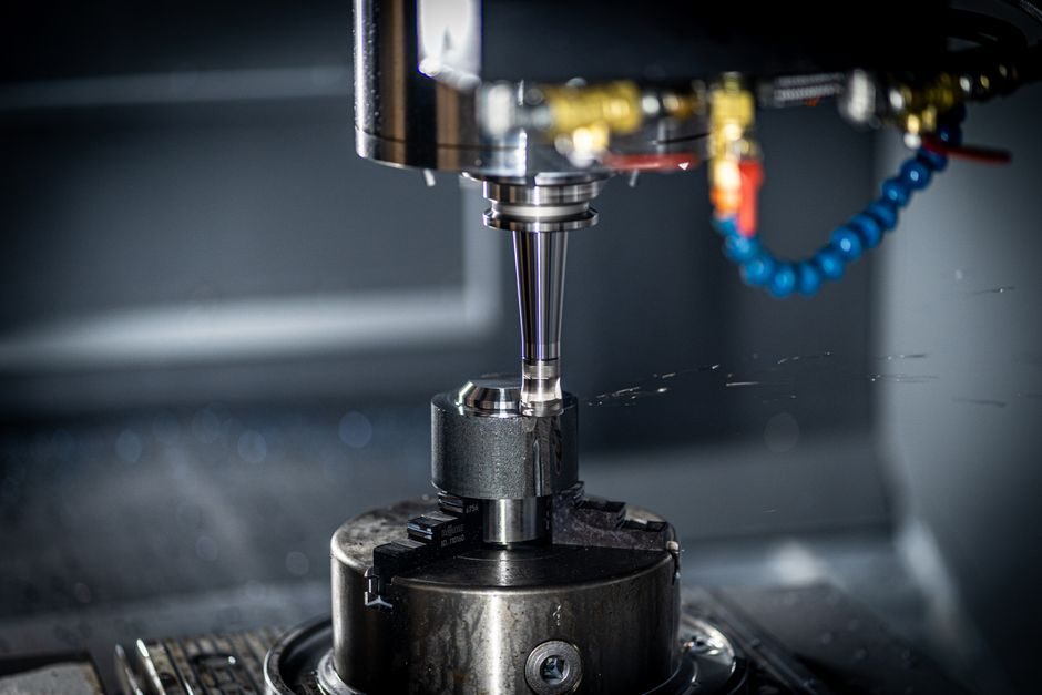
A hydraulic cylinder converts fluid pressure into linear force, and the manufacturing workflow — bar stock prep, barrel honing, rod plating, machining, assembly and proof testing — is dictated by bore size, pressure rating and duty cycle, with custom and standard lines running in parallel across the industry [S1][S2].
Process scope covers material selection (typically cold-drawn seamless tube such as 20# / 45# carbon steel and chrome-plated 45# / 40Gr piston rods), CNC machining of barrel bores and seal grooves, multi-stage telescopic designs with strokes up to 12,500 mm, and acceptance testing on every unit before shipment [S3].
Bill of Materials and Bar Stock Selection
Cold-drawn seamless carbon-steel tube (commonly 20# or 45# to GB/T standards) is the default barrel stock for agricultural and construction cylinders, while piston rods are supplied as 45# or 40Cr alloy steel, hard-chrome plated after grinding to a typical surface finish of Ra 0.2–0.4 µm and a plating thickness of 20–30 µm for corrosion and wear resistance [S3].
Seal-groove dimensions, end-cap mounting style (tie-rod, welded, or flanged) and wiper/rod-seal choices are selected from the application pressure class; standard agricultural multi-stage cylinders use single- or double-acting configurations with shaft diameters from 10 mm up to 280 mm to cover the full range of tractor and tipper-truck kinematics [S3].
Barrel Boring, Honing and Surface Finish
Barrel stock is rough-bored on a lathe or deep-hole drill, then finish-honed to the target bore tolerance and a surface roughness typically between Ra 0.2 and Ra 0.8 µm; this finish directly controls the breakaway friction and the wear rate of the piston seal under cyclic load. [S3]
For telescopic (multi-stage) cylinders, each successive stage is machined to a tighter concentricity (commonly within 0.05–0.10 mm TIR) so that the stages slide freely under side-load without galling, and a honing stone with a finer grit (e.g. 600#) is used on the final stage to support the dynamic seal [S3].
Piston-Rod Hard Chrome Plating and Grinding
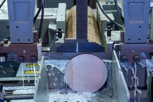
The piston rod is ground to its final diameter before plating, then hard-chrome plated to a specified thickness — typically 20–30 µm for industrial cylinders, 25–50 µm for mining and mobile-equipment duty — and finished by a second precision-grinding pass to restore roundness and surface finish. [S3]
Hard-chrome plating (commonly to ISO 6158 / equivalent specifications) provides corrosion resistance, wear life and a controlled surface for the rod seal; austchrome and other reclamation shops strip and re-plate rods during repair to restore original dimensions rather than scrapping the assembly [S8].
End-Cap, Piston and Seal-Groove Machining
End caps, gland nuts and pistons are CNC-turned from forged or bar-stock blanks, with seal grooves machined to match the selected seal profile (e.g. O-ring, U-cup, step seal or piston composite set); groove depth and width are usually held to ±0.05 mm to avoid extrusion at rated pressure.
For tie-rod cylinders, high-tensile tie-rods (typically Grade 8.8 or higher) clamp the end caps against the barrel, and torque is applied in a criss-cross pattern to a value specified by the cylinder manufacturer; welded cylinders skip the tie-rods and use a fusion-welded cap-to-barrel joint, requiring post-weld stress relief on higher-pressure designs.
Sub-Assembly, Final Assembly and Pressure Testing
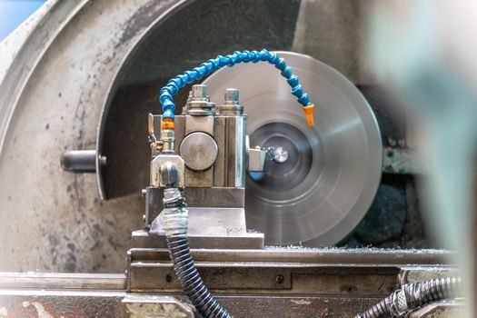
Sub-assemblies are built up on dedicated benches — the piston is fitted to the rod with a locknut or set screw, the piston seals and wear rings are installed, the barrel is loaded, and the gland/cap seals are fitted — before the complete cylinder is piped to a hydraulic test rig. [S1]
Every production cylinder is proof-tested, typically at 1.5× the rated working pressure (and held for a defined dwell, often 1–3 minutes), with leakage and external-seal-pass criteria checked against the manufacturer's standard; repair shops apply the same test sequence after rebuild, in addition to rod-chrome thickness measurement and surface-finish verification [S5][S8].
Custom vs Standard Production: Two Parallel Tracks
Manufacturers typically run two parallel flows: a standard line (e.g. NFPA tie-rod cylinders in fixed bore/rod combinations) for inventory and short lead-time, and a custom engineering line (e.g. PTE's SLM/SLH/SLP/SHP series, Hänchen's special-machine units) where bore, stroke, mount, sealing and pressure are configured per order [S1][S2].
On the custom side, engineering deliverables include duty-cycle analysis, seal selection, mounting-style choice and acceptance-test scope; on the high-volume side, suppliers such as HDM focus on small-diameter cylinders in large batches with matched seal kits to simplify field maintenance [S4].
Repair, Reclamation and Re-Chroming
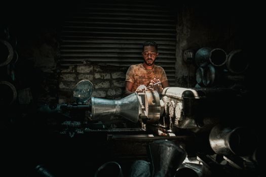
The repair flow mirrors the manufacturing flow in reverse: inspection, disassembly, rod-chrome strip and re-plate, barrel re-hone or sleeve, seal-kit replacement, reassembly and the same proof test used for new cylinders [S5][S8].
Industrial repair shops cover mining, agriculture, defence, heavy industrial and mobile-equipment cylinders, with thermal reclamation used on worn rod surfaces where grinding alone cannot restore geometry; this makes the rebuild a viable alternative to replacement when the barrel and end caps are still within dimensional limits [S8].
Quality Gates and Engineer Selection Criteria
Four criteria reliably separate a competent hydraulic-cylinder manufacturer from a marginal one: (1) material traceability (mill certs for tube and rod, plating thickness records); (2) bore-and-rod dimensional capability (typical bore tolerances ±0.025–0.05 mm, rod straightness ≤0.05 mm/m); (3) 100% proof-test at 1.5× working pressure with documented hold time; (4) seal-groove geometry verified against the actual seal part-number, not a generic drawing. [S3]
Buyers should also weigh lead time (custom cylinders commonly run 25–40 days for export orders against 5–10 days for standard catalogue units), the manufacturer's pressure-class ceiling, and the availability of matched seal kits for in-service maintenance [S3][S4][S6].
Selection: Who Standard Cylinders Fit, and Who Needs Custom
Standard NFPA-style tie-rod cylinders fit most general industrial presses, machine tools and clamping fixtures where bore, stroke and mount match a published catalogue; custom engineering is the right route for pressures above the standard line's ceiling, for unusual mounting geometries, for severe-environment media (e.g. marine, food-grade, mining slurry), or for integrated sensors and special sealing. [S1]
For mobile equipment — agricultural tippers, refuse trucks, dump trailers — telescopic (multi-stage) cylinders in 20# / 45# steel with chrome-plated 45# / 40Cr rods are the dominant pattern, and suppliers such as Shandong-based OEMs offer bore/rod combinations to 280 mm shaft diameter and 12,500 mm maximum stroke on a 5-piece MOQ with monthly capacity around 10,000 pieces [S3].
Designers evaluating related motion components should cross-check the hydraulic actuator reference, the hydraulic motor reference for the rotary side of the circuit, and the hydraulic cylinder spec page for bore/rod/pressure class tables.
Trackable signals for the next planning cycle: (a) supplier disclosure of test-rig pressure and hold-time values on data sheets, (b) wider availability of matched seal kits for legacy bore sizes, and (c) growth in small-bore high-volume production for robotics and AGV-class actuators [S4][S6]. For adjacent heavy-equipment cost analysis, see the steel-strand total-cost-of-ownership reference.