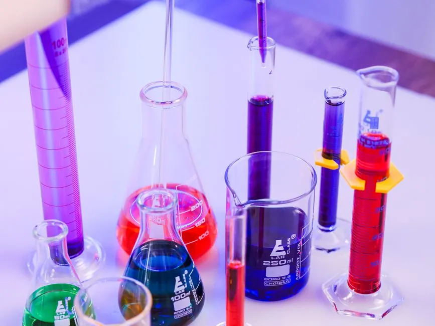
Hyperscaler data centers now consume 1.5 million to 3 million gallons of water per day for cooling at facilities rated 100 MW to 300 MW, and modern GPU chips draw 6–10x the power of their 10-year-old predecessors, forcing the transition from air to two-loop liquid cooling [S2].
The instrumentation stack that supports this transition breaks into five measurement families: flow, pressure, level, leak detection, and analytical (coolant quality), all tied to a control platform that is increasingly built on industrial PLCs rather than open-source or custom boards [S1][S4].
Five Measurement Families Inside the Liquid Loop
Flow measurement is treated as the most critical variable in any liquid cooling system, because coolant mass flow directly sets heat removal capacity at the chip or rack level [S1].
Common flow-metering points are the Coolant Distribution Unit (CDU) outlet, the secondary loop branch feeding each rack, the chilled-water header, and the heat-exchanger return line. Pressure transmitters sit on the same points to flag filter fouling, pump degradation, and valve mis-positioning, while level sensors on coolant storage tanks and expansion vessels prevent pump cavitation and confirm refill readiness [S1]. Leak detection cabling is installed under raised floors, around CDUs and pumps, along pipe racks, and near storage tanks, because even a small dielectric or glycol leak can take a high-density rack cluster offline [S1]. Analytical sensors cover conductivity, pH, and particulate counts to track coolant chemistry drift over the loop's service life [S1].
This stack maps cleanly onto standard process control practice, where the same five measurement families are used on chemical, power, and HVAC loops, but with tighter response-time targets because server return-water temperatures shift within seconds under bursty AI workloads.
Two-Loop Topology: Secondary Inside, Primary at the Facility
Liquid cooling in a modern data center is built as a closed secondary loop inside the white space, discharging heat to a facility-level primary chiller loop that ties to industrial chillers and external heat exchangers [S2].
The secondary loop carries treated or purified water (or a water-glycol mix) at controlled inlet temperatures, typically into the cold plate or immersion tank, and returns warmed fluid to the CDU. The CDU isolates the two loops hydraulically and thermally, so a pressure or chemistry event on the facility side does not propagate into the IT white space [S2]. Process instrumentation on the primary side is what engineers classically associate with process control: flow, level, and analytical on the chiller barrel, plus differential pressure across the heat exchanger.
Instrumentation redundancy on the secondary side is the more recent change, because AI workloads tolerate minutes of degradation rather than hours, and a single failed transmitter can force a rack throttle.
Why Industrial PLCs Beat Open-Source and Custom Boards
Open-source control platforms are widely used in early-stage liquid cooling prototypes, but they typically lack native support for Modbus TCP/IP, BACnet/IP, and EtherNet/IP, and run general-purpose operating systems that introduce latency and instability under real-time load [S4].
Custom control boards solve flexibility problems at the cost of long-term serviceability: every firmware revision and EMC/EMI compliance test has to be re-qualified, which does not scale across hundreds of CDUs [S4]. Industrial PLCs are engineered for harsh-environment operation, support the protocols that building management and data center infrastructure management (DCIM) systems actually speak, and ride out power interruptions without memory corruption [S4]. For mission-critical AI and HPC sites, the PLC route is the baseline rather than the option.
For sites that also drive lamps and light fittings on the same building bus, BACnet/IP support on the same PLC platform lets one controller cover both the cooling and the lighting/electrical scopes.
Selection Criteria: Matching Sensor to Loop Position
Sensor selection on a liquid cooling loop is governed by four decision axes: wetted-material compatibility with the coolant, accuracy class at the operating flow rate, response time, and protocol integration with the PLC [S1][S4].
On the secondary side, ultrasonic or Coriolis flow meters are common at the CDU outlet because they have no moving parts and tolerate the treated-water chemistry; on the primary side, electromagnetic flow meters are widely used on chilled-water headers for the same wetted-material reason. Pressure transmitters are typically specified with 4-20 mA plus HART, so a single analogue pair carries both the process variable and the diagnostic data into the PLC. For a structured comparison:
Sensor type vs decision criterion:
1. CDU outlet flow: Coriolis or ultrasonic, accuracy class 0.5% or better, HART or Modbus, wetted parts in stainless or alloy compatible with treated water.
2. Primary loop flow: electromagnetic, accuracy class 1.0% typical, HART or Modbus TCP, lined body for water service.
3. Differential pressure across filter or heat exchanger: 4-20 mA plus HART, ranges selected for 0.5–2.5x working pressure to keep resolution useful.
4. Tank level: hydrostatic or guided-wave radar, HART, redundant point for backup-tank confirmation.
5. Leak detection: conductive or fiber-optic sensing cable under the floor, switched or analogue output back to the PLC discrete module.
This is also where process calibration discipline matters: a 1% flow error at the CDU scales into a noticeable rack-inlet temperature error under high heat flux, and that error is exactly the one AI training jobs cannot tolerate.
Failure Modes Engineers Actually Plan For
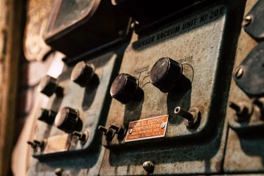
The recurring failure modes on operating liquid cooling loops are: filter fouling (flagged by rising differential pressure), pump cavitation (flagged by tank level drop and pressure oscillation), coolant chemistry drift (flagged by conductivity and pH), and slow leaks under raised floors (flagged by leak detection cable) [S1].
Each of these maps to a sensor family and a PLC logic block, and each one is also the kind of pre-failure signal that supports a predictive maintenance ticket in the DCIM rather than an emergency shutdown. The instrumentation is therefore not a passive meter stack; it is the input layer for a control strategy that decides when to throttle a rack, when to backflush a filter, and when to alert an operator [S1][S4].
For more on the upstream side, the AI accelerator line design wafer, HBM, and compute tiering spec map covers the chip-level heat flux that drives these loop requirements, while the HBM manufacturing equipment spec guide covers the thermal constraints on the memory stack that sits next to the GPU.
Standards, Sourcing, and What to Verify on a Datasheet
Engineers specifying sensors and PLCs for liquid cooling should verify four things on the datasheet: wetted-material compatibility with the specific coolant (treated water, water-glycol, or dielectric fluid), the supported industrial protocol list (Modbus TCP/IP, BACnet/IP, EtherNet/IP, PROFINET), the EMC/EMI compliance class, and the mean time between failures (MTBF) figure for the operating temperature range [S4].
On the control side, confirm redundant PLC processor configuration, hot-standby switchover time, and how the controller publishes data to the DCIM layer. Specifications that omit any of these four items are a flag to dig deeper or run an on-site audit before sign-off [S4]. The multifunction process calibrator role in commissioning is to verify the 4-20 mA, HART, and Modbus loops at the panel before the CDU is handed over to operations.
Trackable next signals: hyperscaler facility water-use disclosures, PLC vendor announcements of native liquid-cooling reference architectures, and OCP (Open Compute Project) liquid cooling spec revisions that name specific sensor and protocol classes.