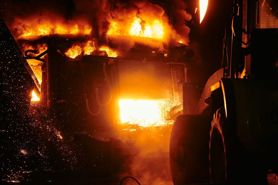
An industrial melting furnace installation is a multi-stage engineering job — civil, electrical, water-cooling, crucible or coil prep, and a controlled first-heat commissioning — where mismatched sequencing accounts for the majority of first-year downtime events documented across induction, gas, and vacuum furnace classes [S2][S4].
Specifying engineers in 2026 typically select between medium-frequency induction (KGCL-type power supplies 10 kW to 50,000 kW), gas-fired crucible, and vacuum induction units, with copper, aluminum, and steel foundries choosing different duty-cycle profiles (1-100 kg benchtop up to multi-ton scrap melters) [S4][S7]. Residential gas units occupy a different cost band entirely at $3,800-$12,000 installed and are excluded from the industrial scope below [S1].
Match the Furnace Class to Alloy and Duty Cycle
Selecting the wrong furnace class for the target alloy is the single most expensive install error; copper and brass mills running 50/60 Hz medium-frequency units with vertical semi-continuous casting downstream report significantly different refractory wear patterns than steel-melt SCR parallel intermediate-frequency furnaces on the same foundry floor [S2][S3].
For ferrous melts (steel, iron), SCR series or SCR parallel intermediate-frequency furnaces with thyristor control and a series-inverter "one power supply drives two furnaces" topology dominate the 2026 catalog offerings, with reported working-status and fault display built into the cabinet for simplified maintenance [S3]. Non-ferrous foundries handling copper, brass, and aluminum typically pair medium-frequency furnaces with screw-type or vertical semi-continuous casting units sized to 1200×650 mm copper strip formats [S2]. Specialty alloys and high-purity reactive metals route to vacuum induction melting furnaces (VIM) where chamber pressure control is mandatory, while axial-gun electron-beam melting furnaces handle refractory and high-melting-point materials where the gun chamber is independently evacuated to allow the melting chamber to run 1-2 orders of magnitude higher in pressure than the gun chamber [S8]. For an overview of gas-fired options suited to aluminum, see the gas aluminum melting furnace reference page.
Site Prep: Foundation, Ventilation, and Utility Drops
Industrial medium-frequency furnace foundations must be sized for the dynamic load of the molten metal bath plus the coil/crucible assembly — a 1-ton iron pour produces a static load well above 2,000 kg on a footprint typically 1.5×1.5 m, and dynamic stirring forces from the induction coil add horizontal vibration that an unreinforced industrial slab will not survive a year of cyclic heating. [S5]
KGCL power supplies for induction melting furnaces range from 10 kW benchtop units to 50,000 kW for foundry-scale applications [S4]. For plants also handling downstream casting, a crucible furnace comparison helps clarify which heat-source family maps to which ventilation duty.
Electrical Commissioning: Power Supply, Coil, and Bus-Bar
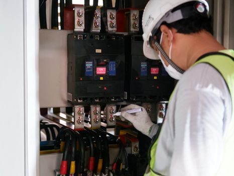
KGCL-series power supplies from induction furnace OEMs in the 10-50,000 kW band accept 50/60 Hz mains and convert to the medium-frequency output the coil requires, with one-supply-two-furnace (commonly "one drive two") inverter configurations now standard for new energy-saving series intermediate-frequency electric furnaces [S3][S4].
Commissioning steps the 2026 OEM documentation treats as mandatory before first heat: (a) megger the coil-to-ground at 1,000 V DC and verify insulation resistance > 100 MΩ; (b) phase-rotation check on the DC bus, because reversed rotation on a SCR parallel unit will fault immediately on ramp; (c) water-flow interlock test — the contactor must trip with flow below the nameplate L/min before RF is enabled; (d) capacitor bank tuning to the installed coil inductance, since a retuned coil after refractory change is a common cause of "won't reach rated power" complaints. Reference the melting furnace page for the cross-vendor power-supply naming conventions used in catalogs from byqdl, furnacescn, and aps-furnace.
First-Heat Procedure and Acceptance Criteria
A controlled first-heat ramp — typically 4-6 hours of low-power drying of the crucible or refractory lining before any metal is charged — separates a successful installation from a lining that spalls on day 30; OEM datasheets for 50/60 Hz 70 kg high-frequency benchtop units and 1-100 kg high-capacity steel/iron/copper/aluminum units both specify a low-power dry-out curve before alloy loading [S7].
For facilities also installing a cupola furnace line, a parallel first-heat protocol applies but with additional blower and tuyeres verification.
Common First-Year Failure Modes and When to Escalate
Three failure modes account for the bulk of first-year service calls on industrial melting furnace installations: (1) refractory cracking from skipped or rushed dry-out, which is repairable on-site up to about 30% of the lining depth but triggers full re-line beyond that; (2) coil-to-ground leakage from cooling-water conductivity creep, which demands water-quality review and may require deionized loop upgrade before re-energizing; (3) SCR/thyristor fault trips on ramp, which typically trace to capacitor bank detuning after a coil or lining change and which the OEM cabinets are designed to flag via built-in fault display [S3].
Escalation triggers the OEM service bulletins consistently flag: any water leak inside the coil former; any fault code that recurs after a documented reset; any audible arc or visible flash at the bus bars. Beyond these, the right move is OEM field service rather than in-house repair, since medium-frequency capacitor banks retain dangerous charge for several minutes after the supply is isolated. For plants also rolling out a belt tensioner sizing program on the same line, the same first-year audit discipline applies across drives. A complementary cross-equipment installation reference is the rebar cutter installation guide, which mirrors the dry-out / first-cut acceptance logic in a different process domain.
Trackable next signals: monitor (a) lining life in heats per lining set against OEM warranty hours, and (b) specific energy kWh/ton per shift against the commissioning baseline — a drift of more than 10% in either metric is the trigger for a coil-and-capacitor re-tune.