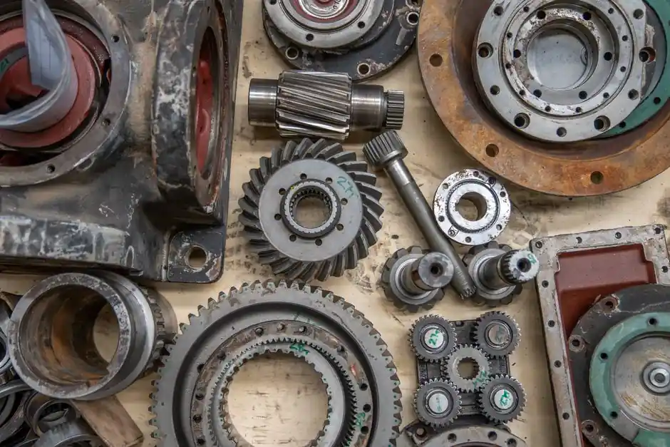
Automotive parts foundries specifying melting equipment in 2026 converge on medium-frequency coreless induction furnaces sized between 0.5 t and 10 t per unit, with power ratings from 250 kW to 3,000 kW and operating frequencies in the 1-20 kHz band [S6]. The driver is batch-mix flexibility: induction units let a foundry switch between carbon steel, alloy steel, and ductile iron without the slag-composition reset that a cupola furnace requires.
Three families dominate the automotive supply chain: coreless medium-frequency for steel and iron melt shops, channel-type holding units for pour-line buffering, and vacuum or inert-atmosphere variants for specialty alloys. Selection starts with the alloy matrix, the batch weight, and the production cadence, not with the brand name on the cabinet [S2][S4].
Coreless Medium-Frequency Units: Default for Steel and Iron
Coreless medium-frequency induction furnaces convert three-phase mains through a rectifier into DC, then into a 1-20 kHz alternating current that drives a water-cooled copper coil surrounding a refractory-lined crucible [S6]. This topology melts 0.5-10 t batches of steel or iron in 45-90 minutes depending on power density, which typically runs 250-400 kW per tonne for steel scrap melting.
Foundries pouring crankshafts, axle housings, brake rotors, and differential cases standardize on this class because stirring from the induced current produces a homogeneous melt without external electromagnetic pumps [S4]. Crucible lining choices split between silica (acid service, iron-heavy alloys) and alumina-magnesia (basic service, steel with low residual Al), with reline intervals of 300-1,200 heats depending on bath temperature (typically 1,500-1,650 °C for steel) and slag chemistry.
Selection Criteria: Frequency, Power Density, and Lining
Selection criteria for an automotive parts melt shop can be reduced to four numbers: capacity (tonnes per unit), melting rate (tonnes per hour), specific power (kW per tonne), and frequency (Hz or kHz). Higher frequency (5-20 kHz) suits smaller melts and shallow baths because it concentrates eddy-current heating near the surface, while lower frequency (150-1,000 Hz) drives deeper stirring for larger steel batches [S6].
For automotive parts, the practical comparison is coreless medium-frequency versus channel-type holding and versus crucible furnace топologies. A two-furnace layout, one coreless melter plus one channel holder, is the most common 2026 automotive configuration.
Who It Is For and Who It Is Not For
Induction melting fits automotive parts foundries with batch weights from 200 kg to 10 t, mixed alloy schedules, and quality programs that demand tight chemistry control. It does not fit high-tonnage continuous iron production where a cupola furnace or shaft furnace delivers lower specific energy, and it does not fit copper or aluminum automotive components, which are better served by gas-fired melting furnace or resistance-holding units due to conductivity and oxide-loss economics [S4].
Foundries running fewer than 8 heats per day also struggle to justify the rectifier-and-capacitor-bank capital cost of medium-frequency coreless units; in that throughput band, a crucible furnace with externally heated chamber often has the lower lifecycle cost. Conversely, a three-shift operation pouring 60-120 t/day of iron or steel in mixed grades is exactly the operating envelope where coreless medium-frequency induction earns its premium.
Use Cases: Crankshafts, Brake Rotors, and Axle Castings
Automotive crankshaft lines in 2026 typically run 1-3 t ductile iron batches at 1,420-1,480 °C, with melt-to-pour cycle of 50-70 minutes in a 1,500 kW coreless unit at roughly 8-10 kHz. Brake rotor and disc lines lean toward 0.5-2 t gray iron batches in 800-1,200 kW furnaces at 6-10 kHz, where the higher frequency tightens the skin depth for the smaller bath diameter. [S2]
Steel component foundries (transmission gears, axle shafts, steering knuckles) pour 1-5 t of medium-carbon or low-alloy steel at 1,580-1,640 °C from 2,000-3,000 kW medium-frequency furnaces, with desulfurization and nodularization handled in ladle transfer rather than in the furnace bath. The induction furnace topology gives these shops the rapid grade-change capability their mixed-model programs demand [S2].
Limitations, Failure Modes, and Standards
The principal failure modes of a coreless medium-frequency induction furnace are coil-water leak (usually at a brazed joint after 8,000-15,000 heats), refractory wear at the slag line (visible as a deepening meniscus), and capacitor-bank imbalance when one phase degrades. Power supply reliability metrics typically target 99% uptime over a 12-month window; water cooling system design should follow the manufacturer's flow and conductivity specifications to prevent copper oxidation inside the coil [S4].
Relevant standards include IEC 60079 for hazardous-area electrical equipment classification around molten metal handling, and IEEE 519 for harmonic distortion limits on the medium-voltage supply feeding the rectifier. Foundries exporting to European automotive OEMs should also confirm CE machinery directive compliance and RoHS status on the power-electronics components. Operator electrical safety requires interlocked access doors and a documented lockout-tagout procedure per OSHA 29 CFR 1910.147 in North American facilities.
Supplier Landscape and Spare-Parts Sourcing
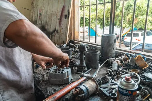
The 2026 automotive induction furnace supplier base splits between Chinese manufacturers (Yinda and a long tail of medium-frequency specialists), Indian vendors (notably in the Faridabad and Ahmedabad industrial clusters supplying induction furnace spares such as coils, capacitors, hydraulic yokes, and thyristor modules), and European engineering firms focused on higher-power and vacuum units [S2][S5]. Spare-parts lead time for a coil is typically 6-10 weeks from a Chinese OEM and 4-6 weeks from a domestic Indian vendor.
For a foundry building a new line, the practical selection sequence is: (1) lock in alloy matrix and batch size, (2) calculate required melt rate from production schedule, (3) match specific power and frequency to bath geometry, (4) confirm refractory lining compatibility with the highest-melting alloy in the schedule, and (5) budget a two-furnace layout if the daily tonnage exceeds 40 t. The trade-off between coreless melter and channel holding furnace ultimately tracks pour-line temperature stability targets, and for foundries serving brake and chassis component programs, a 1,500-2,500 kW coreless medium-frequency unit paired with a 200-500 kW channel holder remains the dominant 2026 reference design. Foundries evaluating related equipment such as cranes for the melt-shop bay can cross-reference truck crane selection for demolition projects, while those also pouring non-ferrous housings will want to read melting furnace selection for electronics housings.