
Tool and component coatings are the most cost-effective route to higher productivity in machining and to longer service life in corrosive plant equipment, with chemical vapor deposition (CVD), physical vapor deposition (PVD), and plasma-assisted chemical vapor deposition (PCVD) representing the three dominant deposition families [S6].
Across the cutting-tool industry, coated inserts are now the default rather than the exception because a single 2-10 µm ceramic or nitride film can multiply tool life by 3-10× on difficult-to-machine titanium and nickel-base superalloys, while surface roughness of coated parts typically drops by 30-50% versus uncoated reference [S6]. A broader reference frame on coating categories and their operating envelopes is maintained in the industrial coating encyclopedia entry.
What an industrial coating actually does
Industrial coatings modify the top 1-15 µm of a substrate to add wear resistance, oxidation resistance, chemical barrier, thermal barrier, or dielectric behaviour, depending on film chemistry [S6]. The three principal deposition routes — PVD, CVD, and PCVD — differ in process temperature, coating chemistry, throwing power, and how the film bonds to the substrate.
PVD processes (sputtering, cathodic arc, electron-beam evaporation) typically run at 200-600 °C and produce nitride or carbonitride films such as TiN, TiAlN, CrN, and DLC; this low thermal budget makes them the default for hardened tool steels (HRC 60+) and high-speed steel that would soften above 550 °C [S6]. CVD operates at 700-1050 °C and deposits TiC/TiN/Al₂O₃ multilayers with excellent throwing power into holes and slots, which is why indexable inserts for turning and milling are dominated by CVD multilayers [S6]. PCVD sits between the two in temperature (500-750 °C) and combines plasma activation with CVD chemistry, lowering the deposition temperature while keeping a CVD-like composition range [S6].
Decision criteria when selecting a coating
Specifying a coating is a four-variable decision: substrate temperature limit, geometry, service environment, and cost-per-wear-hour, not a single "best coating" choice [S6]. The same source documents the trade-off between coating adhesion, residual compressive stress, and maximum usable film thickness; once thickness exceeds roughly 10 µm, residual stress drives spallation on most steel substrates.
For HSS tooling and cold-work tool steel, TiN and TiAlN PVD films at 2-4 µm dominate because the substrate cannot survive CVD temperatures. For carbide inserts in finishing and roughing, CVD TiCN/Al₂O₃ stacks at 6-12 µm are the workhorse. For complex-geometry cutting tools (drills, taps, end mills) where the workpiece has deep flutes, PVD's line-of-sight limitation must be compared against CVD's conformal coverage [S6]. For related context on surface protection in process plant service, the waterproof coating reference maps barrier-film chemistry onto immersion and splash-zone service.
Comparison of PVD vs CVD vs PCVD
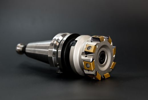
The three deposition routes line up against four decision criteria: process temperature, throwing power, typical film thickness, and chemistry range. PVD: 200-600 °C, line-of-sight only, 1-5 µm, nitride/carbonitride/DLC. CVD: 700-1050 °C, fully conformal, 5-15 µm, carbide/nitride/oxide multilayers. PCVD: 500-750 °C, moderately conformal, 3-8 µm, carbide/nitride/oxide [S6].
Throwing power is the make-or-break criterion for tooling with deep flutes, radii, or through-holes: a PVD arc can miss a flute bottom by 30-60% in film thickness, while CVD over the same geometry lands within roughly ±10% [S6]. PCVD closes part of that gap because the plasma activates reactant gas into recessed surfaces, but it still does not match the throwing power of high-temperature CVD on internal coolant-channel tooling.
Coating selection also depends on whether the engineered film must be a thermal barrier, a wear barrier, or a chemical barrier. Al₂O₃ CVD films carry continuous-service temperature capability above 900 °C in oxidising atmospheres, which is why they are layered on carbide inserts for high-speed turning of nickel-base superalloys [S6]. Where a metal-finishing or assembly line needs non-metallic barrier protection instead, the industrial adhesive reference maps bonding chemistries onto similar substrate-temperature and chemical-exposure criteria.
Who should specify a coating, and who should not
Engineers specifying coated tooling for high-volume machining, or specifying internal coatings for tanks, valves, and process piping in corrosive service, are the primary use cases; end-users buying consumer hardware do not have the substrate-temperature or process-gas data to make this decision and should rely on supplier specification [S6]. A coated cutting tool only outperforms an uncoated tool when cutting temperature, chip load, and workpiece material all fall inside the film-design envelope — for example, uncoated HSS drilling of aluminium at low speeds often outlasts a misapplied TiAlN film because the coating can gall.
Conversely, in chemical, marine, and oil-and-gas service, an internal coating or a lined pipe routinely delivers 15-25 years of maintenance-free service versus 5-10 years for bare carbon steel, so specifying a coating is rarely optional in those exposure classes. Where a buyer is comparing a coated part against a lined part, the substrate-temperature limit, cure temperature, and repairability after field damage become the gating criteria, not the chemistry name [S6]. For comparison context on how alternative surface-engineering routes perform on different substrates, the ceramic bearing trade-off map is a useful parallel reference.
Limitations, failure modes, and inspection

Coating failure modes fall into four buckets: spallation from residual stress, decohesion at the substrate interface, through-thickness wear, and chemical attack on the film itself. Residual compressive stress above roughly 2-4 GPa in a thick PVD film is the usual spallation driver; CVD α-Al₂O₃ and TiCN multilayers are more tolerant because residual stress is lower and the layered structure arrests crack propagation [S6].
On coated cutting tools, the end of life is signalled by crater wear on the rake face exceeding roughly 0.3 mm, flank wear exceeding 0.3-0.5 mm, or coating spall exposing substrate. For non-cutting service, qualified inspectors use a coating thickness gauge in the 0.5-20 µm range and verify continuity with a holiday detector at 5-67 V DC depending on film thickness — equipment mapping for that gauge is in the coating thickness gauge reference. For internal inspection of coated tanks and pipes where the coating may have blistered or cracked, an industrial borescope rated for the chemical service is the standard verification tool, with porting and probe options catalogued in the industrial borescope reference.
Standards, sourcing, and supply-side signals
Coating procurement should reference ISO 14586 for CVD/PVD film thickness on cutting tools, ISO 27874 for general thin-film thickness by X-ray fluorescence, and ISO 9227 for salt-spray rating when corrosion resistance is on the datasheet; corrosion-related process equipment should also be checked against NACE MR0175 for sour-service exposure [S6]. Coatings qualified to these standards ship with a measured thickness certificate, a hardness value (typically 1500-3500 HV for nitride films), and a maximum service-temperature rating.
Supply-side, the 2025-2026 capacity additions sit in PVD arc-evaporation and HIPIMS lines, not in CVD reactors, because of lower capex and faster recipe changeover. For engineers mapping deposition technology to battery electrode coating, the EV battery cell quality spec map is a useful cross-reference. Two trackable signals for the next planning cycle: (1) whether your coated-tool supplier publishes film chemistry beyond the brand trade name — anything less than a stated compound, thickness, and max service temperature is a spec gap; (2) whether the coating line is certified to ISO 9001 with a documented calibration programme for the thickness gauge that will be used to accept incoming coated parts.