
Generator selection for industrial and commercial sites is governed by four hard inputs: connected running kW, peak motor-starting kVA, allowable voltage dip, and the NEC article class of the installation (700 emergency, 701 legally required standby, 702 optional standby) [S5].
OEM sizing platforms such as Generac Power Design Pro and the Cat commercial generator sizing calculators model concurrent and non-concurrent motor starting, harmonic spectrum, and load shedding before any conductor or breaker call-out is made [S1][S4].
Define Duty Class and NEC Article Before Touching kW
Generators are not interchangeable across duty classes. NEC Article 700 covers emergency systems where failure could cause life-safety hazards, Article 701 covers legally required standby, and Article 702 covers optional standby where the user accepts the risk of outage [S5]. The article chosen drives the transfer-switch type, the maximum allowable pickup time, and the on-site fuel reserve rule, all of which feed back into the kW rating you must specify [S2]. A 500 kW unit specified for Article 700 will not be the same physical machine (controller, fuel tank, and ATS family) as the same 500 kW rated for Article 702, even though the running load is identical.
For sites that depend on the genset as the prime source of power (no utility parallel), the sizing math starts again from prime ratings, not standby ratings, and continuous running power is derated further for altitude above 1000 m and ambient above 40 °C [S2].
Build the Load List: Running kW, Peak kVA, and Harmonic Content
Step one in any credible sizing is a structured load list with three columns per device: running kW, starting kVA (or locked-rotor kVA), and power factor [S2]. Resist the temptation to use simple HP-to-kW conversion. A 50 HP motor at 460 V typically draws around 65 A full-load, and during across-the-line starting it can demand 6× to 8× that current for 3 to 10 seconds, which is what stresses the alternator [S5].
Harmonic loads must be flagged separately. UPS systems, VFDs without line reactors, LED driver banks, and switch-mode power supplies inject current harmonics that the generator must supply without exceeding a stated total harmonic voltage distortion (THVD) limit at the bus [S1]. Power Design Pro exposes THVD as a sizing-criterion field, alongside voltage dip and frequency dip at both project and per-sequence level [S1].
For complex industrial sites with chilled-water plants and process skids, the same OEM tools offer advanced models for soft starters, VFDs, UPS, and chillers rather than treating them as black-box kW [S1]. This matters because a chiller compressor with a VFD draws far less peak kVA at start than the same compressor on a DOL starter, and oversizing for a fictional peak is a common way to double generator cost.
Compare the Four Main Sizing Approaches Against Decision Criteria
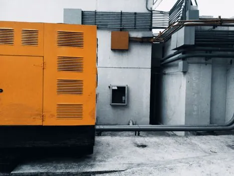
Engineers pick from four approaches, each with clear trade-offs on accuracy, time, and cost [S1][S2][S3][S4][S5].
1. Rule-of-thumb multiplier (3× running kW for motor-heavy sites, 1.25× for mixed). Fast but pessimistic, can over-spec by 40% to 60% on a chilled-water plant, and is not defensible to an AHJ.
2. OEM online calculator (Generac Power Design Pro, Cat sizing calculators). Models load sequences, harmonics, and voltage dip; produces an audit trail; suitable for bids above roughly 100 kW [S1][S4].
3. Vendor factory study. Manufacturer runs a transient simulation with your one-line, load list, and step-loading sequence; required for mission-critical sites, data centers, and hospitals; longest lead time, highest confidence.
4. Manual NEC-only sizing. Used by junior designers who treat NEC as a design manual. The NEC states explicitly that it sets minimum safety requirements, not design guidance, and motor-driven generator sizing is not in its scope [S5]. Use NEC only after the kW/kVA is already set.
Sequence the Motors, Then Size the Alternator
For sites with multiple large motors, the worst case is not the sum of all locked-rotor currents. It is the largest single motor starting while the rest of the plant is already running [S1]. Power Design Pro supports multiple concurrent, non-concurrent, and cyclic starting sequences, so the designer can test scenarios like "chiller 1 starts while chiller 2 and 3 are at 80% load with HVAC online" instead of assuming a single worst step [S1].
Voltage dip is the binding limit in most cases, not frequency dip. A common project limit is 15% voltage dip at the generator terminals during the worst motor start, with 10% often specified for ITE and process loads that will not ride through deeper sags [S1]. Once a candidate genset passes the dip test, confirm that engine kW is still above site running load plus 10% reserve, and that alternator kVA satisfies the largest single step load plus running load at 0.8 power factor.
Fuel and runtime belong in the same review. Standby gensets are usually rated with a fuel tank sized for 8 to 24 hours at full load, while prime sets assume a refuel cadence driven by the on-site fuel logistics [S2].
Environmental, Altitude, and Derating Factors

For tropical sites or rooftop installations in summer, this can cost 15% to 25% of nameplate kW before any load is connected. Sound attenuation adds another sizing consideration: Level 1 enclosures (≈70 dBA at 7 m) are standard, Level 2 (≈60 dBA) for residential adjacency, and critical-grade (≈55 dBA) for hospital and academic campuses, each adding roughly 4 to 8 inches to the enclosure footprint [S2].
For sites with paralleled units, also model load sharing on droop or isochronous mode, and check the kW step load each unit must accept when its peer trips offline [S1].
Common Selection Failures and Who Should Not Use the Mainstream Shortcut
The most common failure is sizing to running kW only and ignoring motor starting, which leads to genset tripping on the first chiller start. The second is sizing to total connected HP without sequencing, which doubles or triples the real peak demand. The third is underspecifying the ATS, picking a unit rated for the running load rather than the locked-rotor inrush, which then welds its contacts on the first transfer. [S1]
Who should not use the rule-of-thumb shortcut: any site with more than one large motor (above 25 HP each), any site with a UPS above 50 kVA, any site in a mission-critical category (NFPA 110 Level 1), and any site that will be reviewed by an AHJ or a utility interconnect engineer [S2][S5]. These sites require either an OEM calculator output with documented assumptions or a vendor factory study [S1][S4].
Shortlist logic: below 50 kW with resistive load, a portable or light-commercial set with rule-of-thumb sizing is acceptable [S3]. From 50 kW to 500 kW with mixed motor load, use an OEM calculator (Power Design Pro, Cat) and a documented load list [S1][S4]. Above 500 kW, prime-rated sites, or paralleled configurations, require a vendor factory study plus an OEM calculator cross-check [S1][S4].
Standards, Codes, and Cross-Reference Points

Generator selection in North America sits on top of NFPA 110 (Standard for Emergency and Standby Power Systems, Levels 1 and 2), NFPA 70 / NEC Articles 700, 701, 702 (system classification), 240 (overcurrent protection), 430 (motors), and IEEE 519 (harmonic limits at the point of common coupling) [S5]. For international projects, ISO 8528-1 defines the duty classes (Continuous, Prime, Limited-Time Running Power, Emergency Standby), and IEC 60034 covers rotating-machine performance. Always tie the final kW number to a named article or standard in the submittal package.
For projects tied to fuel-cell or hybrid BESS additions, expect the OEM sizing tools to evolve: Power Design Pro already lists BESS specification writing as a roadmap item alongside ATS and generator [S1]. Cross-check sizing assumptions against the actual one-line and the harmonic study before release for construction.
Trackable signals to watch: the published update notes for Power Design Pro (BESS module go-live), the next Cat commercial sizing calculator revision, and any revision to NFPA 110 or IEEE 519 that would change the THVD design target.
For component-level specifications, see function generator, linear guide, and crossed roller guide.
Background reading: FIBC Bulk Bag Selection for Apparel Distribution: Type, Size, and Lifting Loop Criteria.