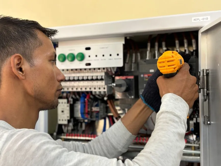
An industrial UPS installation should follow 10 coordinated stages from load assessment through acceptance testing, with a licensed electrician responsible for hardwired work and manufacturer procedures controlling startup and servicing [S2][S5].
Before procuring a UPS, confirm the input and output ratings, battery autonomy, topology, bypass arrangement, ventilation, communications, and compliance with national and local electrical codes for the intended installation [S4][S5].
Load and Runtime: Size Two Separate Requirements
UPS capacity and battery runtime are different design constraints: capacity must support the connected load and power factor, while runtime determines how long that load can operate without normal power [S5]. The planning guide addresses how to size a UPS load and notes that UPS installation requires the attention of a qualified engineer or qualified electrician in some localities [S3].
Power factor expresses how effectively a load uses the supplied VA. The planning example gives 96 W from a 120 VA load as a power factor of 0.8, and 0.8 is a reasonable preliminary assumption when both wattage and VA are unknown [S3]. That assumption is a screening value, not a substitute for a connected-load schedule, startup surge review, or manufacturer sizing method.
For critical applications, size the UPS for the confirmed steady load, critical peak load, transfer behavior, and required redundancy rather than confusing it with an energy-storage duration specification. The battery list must be coordinated with load power, discharge rate, temperature, age, and acceptable end-of-discharge condition [S3][S5].
Site and Electrical Architecture: Fix the Interfaces First
Before delivery, document input voltage, frequency, phase arrangement, output rating, neutral or grounding arrangement, short-circuit interrupting means, bypass design, and communications. The 2U Smart-UPS guide covers models from 750 to 3000 VA at 120/208/230 Vac, including model-specific inventory, rear-panel connections, circuit breakers, SmartSlot, and controlled outlet groups, showing why installation drawings must follow the exact model rather than a generic UPS layout [S4].
Industrial projects must also decide the relationship between the UPS, distribution board, generator, maintenance bypass, static bypass, and downstream protection. Generator compatibility and the maintenance-bypass function should be settled before equipment is ordered, not improvised during shutdown [S5]. The broader electrical review should also address circuit breaker installation and the separation of controls, power, and communication wiring.
For hardwired systems, use a licensed electrician familiar with the selected model and verify the installation against the manufacturer’s manual, approved drawings, and applicable local electrical requirements [S2][S5]. Do not use a generic rack instruction for a floor-mounted, cabinet-mounted, or process UPS with different terminal arrangements.
Physical Preparation: Protect Heat, Moisture, Dust, and Access

UPS battery and ventilation requirements should be addressed during installation planning because installation requirements vary among UPS models, topologies, and deployment methods [S2]. Do not expose the unit to direct sunlight, block vents, or place objects on top of the enclosure; heat, humidity, and dust are recurring installation triggers that should be removed before equipment arrives [S2].
Prepare a floor or rack area for the actual mass and dimensions listed for the selected model. ABB’s TLE Series guide for 160–500 UL S2B equipment provides model-specific weight, dimensions, moving procedures, site preparation, and installation instructions, which should be used for handling and placement rather than estimating from the UPS kVA rating [S1].
Restrict access so cleaners cannot plug loads into the UPS and personnel cannot attach unauthorized equipment. Secure smaller wall-mounted units against service interference, retain the manufacturer’s required working clearances, and provide a safe route for removing modules or batteries.
Delivery and Connection: Treat Movement as a Real Risk
Inspect the shipment before energization and verify model, voltage, battery type, accessories, cabinet condition, and transport damage against the packing list. Connections can shift during shipment, and loose connections can lead to sparking after installation, which can cause charring or fires, so connections should be checked after installation [S2].
Make electrical connections with the UPS isolated as required by its procedure, then perform the manufacturer’s pre-energized checks. The Smart-UPS guide separates inspection, handling, installation, panel features, electrical connection, and controlled outlet-group procedures across the 750–3000 VA model range [S4]. ABB’s TLE guide similarly provides model-specific handling and installation procedures for 160–500 UL S2B systems [S1].
Battery work demands a dedicated isolation and discharge process. The referenced battery replacement procedure begins with powering down and disconnecting the UPS, then removing the old battery where applicable; hazardous AC and DC energy may remain even after utility power is disconnected [S5][S6]. Replace rather than repair a damaged, leaking, swollen, thermally abused, or improperly re-torqued battery assembly, and escalate any internal UPS damage to the manufacturer or qualified service organization.
Topology Selection: Match the Control Strategy to the Load
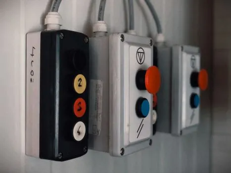
Online, line-interactive, offline, rack-mounted, modular, low-frequency, and mini-UPS designs serve different response, protection, and maintenance needs, so installation complexity cannot be judged from output rating alone [S5]. The available industrial supplier guide distinguishes these families, while its project sequence requires the electrical architecture to be confirmed before the cabinet and battery arrangement are finalized [S5].
This comparison is a selection aid, not a universal ranking. A larger online or modular system is not automatically better for a low-priority load, while a compact rack unit may be unsuitable where continuous double-conversion behavior, expansion, or plant-level bypass control is required.
Commissioning: Test Under Controlled, Recorded Conditions
Commissioning should verify normal operation, bypass transfer, return to normal, battery operation, alarm and event records, output voltage and frequency, load acceptance, and the behavior of configured communications. The 10-stage industrial process includes commissioning and testing after monitoring setup, followed by documentation, training, and maintenance planning [S5].
Test at the intended load and record the results rather than relying on a no-load power check. Include a deliberate utility-loss test, battery discharge test, bypass-transfer test, restoration test, and review of fault annunciation. Stop and investigate unstable output, failed transfer, abnormal alarms, connector heating, battery swelling, or ventilation alarms; do not place the load in service until the cause is corrected or the responsible engineer accepts a documented limitation.
Use the manufacturer’s test limits and acceptance criteria for the exact model. The ABB TLE documentation covers 160–500 UL S2B units, the Schneider guide covers 750–3000 VA Smart-UPS models at 120/208/230 Vac, and the generic industrial guide covers three-phase systems from 10 to 800 kVA [S1][S4][S5]. Acceptance records should identify the serial number, firmware or configuration version, input conditions, load, battery configuration, test result, and corrective action.
Maintenance and Failure Response: Preserve Transferability

Preventive maintenance must preserve the bypass path, battery availability, alarm reporting, and safe service conditions. Factory-recommended service is tied to the manufacturer’s procedure, while a two-to-five-year standard warranty range may apply depending on the model and contract [S2]. The battery replacement sequence remains applicable after initial installation: shut down, disconnect, remove the old battery if required, install and connect the replacement, and test under the prescribed procedure [S6].
Use a symptom-based response: a hot or loose connection requires isolation and electrical inspection, a failed fan or blocked vent requires cooling correction, a low-capacity battery requires measured load and runtime analysis, and an unexplained transfer failure requires topology and bypass testing [S2]. Replace a battery assembly after prolonged heat exposure, physical damage, leakage, or failed capacity testing; do not repeatedly reset alarms or bypass a fault to conceal the underlying condition.
Where remote monitoring is specified, the industrial modem or industrial router provides the communications path, but communication loss does not remove the need for local protection or periodic functional tests [S5]. An industrial UPS installation is complete only when the electrical drawings, test records, battery data, bypass procedure, alarm settings, maintenance schedule, and operator training have been handed over as one controlled package.