An infrared line level is installed by locking the internal pendulum during transport, mounting the unit on a flat surface or tripod, switching on, and allowing 1-2 minutes for the self-leveling mechanism to settle before marking the work surface with tape or pencil [S1][S2].
Typical line laser accuracy spans ±1/8 in to ±1/2 in at 50 ft, working range extends to roughly 300 ft diameter when paired with a detector, and beam color is most commonly red 635 nm or green 532 nm [S1]. For ceiling layouts, multi-line 3x360° or 4x360° models project continuous planes that wrap an entire room, while single cross-line units cover one horizontal plus one vertical axis [S3].
Beam Color, Wavelength, and Indoor vs Outdoor Visibility
Line laser color is set by the diode wavelength: red at 635 nm and green at 532 nm sit near the center of the visible 380-750 nm spectrum, with green perceived by the human eye as up to 400% brighter than red at comparable power [S1]. A red 635 nm source is the default for cost-driven jobs, while a 532 nm green source is the practical choice in well-lit interior work and over longer indoor runs [S1][S3]. Outside, the beam is not visible to the naked eye in daylight regardless of color, and a dedicated laser detector becomes mandatory to recover the line [S1].
When ceiling work is the primary task, beam color is the single biggest productivity lever because the operator is looking up into ambient room light, and reference articles on infrared thermometer wavelength selection note a parallel principle: shorter visible wavelengths read brighter to the eye under ambient illumination.
Laser Class, Power Output, and Safety Envelope
Line lasers are typically Class IIIA devices, with output between 1 mW and 5 mW; Class I and II sit below 0.4 mW to 1 mW, and these are the only classes used for handheld leveling tools [S1]. Class IIIB (5-500 mW) and Class IV (above 500 mW) are explicitly excluded from leveling work because Class IV is hazardous to view under any condition [S1]. Within Class IIIA, a 5 mW unit is brighter and costlier than a 1 mW unit, and operators should avoid staring into the beam even at the legal ceiling [S1].
For site safety, a Class IIIA red or green line laser does not require controlled-area permits in most jurisdictions, but eye protection is still issued on metal-framing and rebar jobs; on those sites, the same PPE envelope that governs an oxy-fuel cutting torch work zone typically covers laser use.
Self-Leveling Mechanism and Manual Mode Lockout

Self-leveling line lasers use an internal pendulum that hangs under gravity and settles inside a window of typically ±4° from true level; the operator must lock that pendulum before transport to prevent damage to the suspension [S2]. On power-up, the device needs 1-2 minutes to find level, and a manual-mode LED is a useful tell: lit means the unit is in tilt mode and self-leveling is disabled, off means the pendulum is active and finding level [S1][S2].
On a sloping block where the floor is not level, a tripod lets the operator raise or lower the beam until it returns to a reference mark, and the unit is then confirmed in level when the secondary corner mark lines up with the projected beam [S2]. This same procedure is used to verify a suspect unit: project the line onto a wall, mark it, rotate the device 180°, and recheck; any offset greater than the published accuracy band (commonly ±1/8 in at 50 ft) means the unit is out of calibration and should be sent for service.
Mounting Options: Tripod, Pole, and Ceiling Clip
Three mounting patterns cover nearly every site condition: a tripod for stable floor work and uneven ground, a telescoping pole mount for fine height adjustment between floor and ceiling, and a ceiling clip that clamps directly onto a drop-ceiling grid [S3]. A pole mount is the right pick when the laser must sit close to the ceiling plane, because a tripod at full extension is unstable and walks under vibration; a ceiling clip is the right pick for grid-work layout because the laser stays co-planar with the T-bar [S3].
For ceiling grid layout, attaching the L-channel (wall angle) directly to the projected laser line removes the need to measure up from the floor at multiple points or to snap chalk lines, which is the single largest time saving on a drop-ceiling install [S3]. This mounting-and-mark discipline is the same logic that drives a good hydraulic motor installation: get the datum plane right, then transfer it once.
Configuration Comparison: Dot, Cross-Line, and Multi-Line Lasers
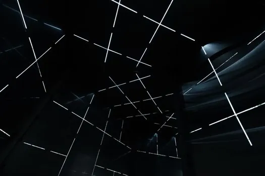
Three configurations dominate ceiling and interior work, and the choice is driven by coverage and visibility, not by accuracy [S3]:
Dot lasers (plumb lasers) project single reference points and are used to transfer floor marks up to the ceiling; they are the cheapest option but require the most manual layout time [S3]. Cross-line lasers emit one horizontal and one vertical beam to form a cross, and they cover general alignment of single fixtures or single runs [S3]. Multi-line lasers at 3x360° or 4x360° project continuous planes that wrap the room and form a 90° reference grid, which is the right pick for placing fixtures in series or for any drop-ceiling layout that needs horizontal alignment without constant repositioning [S3].
For a single-room drop ceiling, a 4x360° green multi-line unit replaces two cross-line units and a second operator, and a representative 16-line model is the CIGMAN CM-S04 with 4x360° green output, full-color LCD, Bluetooth app, and remote [S3]. For a small cabinet or TV-mount job in a domestic room, a single cross-line unit is enough, and the upgrade to multi-line is not justified.
Acceptance Test, Calibration Check, and When to Service vs Replace
Acceptance on site is a two-mark test: project the beam to a wall, mark with tape or pencil, rotate the laser 180° around its vertical axis, and re-mark; the offset between the two marks must fall inside the published accuracy band, commonly ±1/8 in to ±1/2 in at 50 ft [S1][S2]. A second check is the two-corner test: mark the line at one wall corner, move the laser to the opposite corner, re-project, and the new mark must align with the first; if it does not, the offset is the calibration error of the unit at that room scale [S2].
Replace, do not repair, when the pendulum is suspected damaged (a persistent tilt-mode indication after a drop), when the beam flickers or splits, or when the unit fails the two-mark test at any distance inside its rated working range. Service when the unit fails only at the long end of its range, when the manual-mode switch is intermittent, or when the lock mechanism is sticky; these are bench-cleanable issues. For routine use, always lock the pendulum before stowing, and never store the unit in a vehicle overnight in freezing conditions because the diode wavelength drifts and the self-leveling oil thickens, both of which push the unit outside its accuracy band on the first morning beam.
Track these signals on the next site visit: confirm the diode color and class on the nameplate (635 nm red or 532 nm green, Class IIIA, 1-5 mW), confirm the published accuracy figure against the in-field two-mark test, and confirm the working range figure against the actual ceiling height of the next job; if any of the three do not match, the unit is no longer fit for the spec it was bought for.
For the relevant spec sheets and selection criteria, see infrared level, and linear guide.
