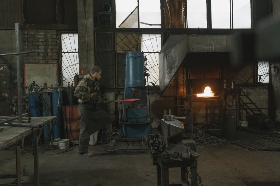
Line-frequency (mains-frequency) induction furnaces operate directly on the 50/60 Hz supply without a static frequency converter, distinguishing them from the medium-frequency (MF) and high-frequency (HF) converter-driven units used in smaller foundries [S2].
Two structural classes — coreless (crucible) and channel-type — cover essentially all mains-frequency melting and holding duty in iron, steel, copper, brass and aluminium foundries, with sub-variants for vacuum, drum, and horizontal continuous casting duty [S3].
Core Architectural Split: Coreless (Crucible) vs Channel (Submerged Heel)
The coreless induction furnace is a refractory-lined crucible wrapped by a water-cooled copper coil, charged from the top and poured by hydraulic or mechanical tilt; the channel furnace bolts a closed-loop molten-metal channel (the "heel") through an inductor and is built around a permanent bath that is never emptied [S3]. Coreless units dominate batch melting of steel, cast iron, copper and aluminium, while channel units dominate holding and duplex melting where the bath remains liquid between shifts. IAS Induction's product taxonomy lists channel and crucible (coreless) variants in parallel for copper, brass, zinc, aluminium, cast iron and steel [S3], confirming that vendor catalogues treat the two architectures as complementary rather than competing for the same duty.
Operating frequency is the first physical fork. A pure line-frequency coreless furnace uses 50/60 Hz directly from the mains through a step-down transformer; medium-frequency (MF) units add a rectifier + inverter stage and typically run at 500 Hz to 1000 Hz, with the Okorder GWG-J series covering 500 Hz (e.g. GWG-1.5-1000/0.5J, 1000 kW rated, 1.2 t/h melt rate) and 1000 Hz (e.g. GWG-1-750/1J, 750 kW, 0.9 t/h) [S1]. That frequency choice is driven by the magnetic skin-depth requirement: at 50/60 Hz the eddy-current skin depth in steel forces very large coil bores and high coil voltages, which is why mains-frequency coreless furnaces are typically 1.5 t and up, while MF coreless furnaces are economical from 0.5 t to 5 t capacity [S1][S2].
Capacity, Power and Energy Bands on Real Equipment
Concrete spec rows from the GWG-J MF coreless series (dual-frequency offerings 500 Hz and 1000 Hz) give the spec engineer a usable price-to-capacity grid: at 1000 Hz, capacity climbs from 0.5 t / 250 kW (0.4 t/h, 770 kWh/t) through 0.75 t / 400 kW (0.6 t/h, 770 kWh/t) to 1.0 t / 750 kW (0.9 t/h, 720 kWh/t); at 500 Hz the same series reaches 8 t / 5000 kW at 500 Hz with 500/550 kWh/t specific consumption [S1]. The 8 t / 5000 kW machine runs on 950 V / 12-pulse input, drawing 3400 A, with a 1250 V DC bus and 7–8 t/h melt rate — typical of heavy steel-mill duty [S1].
Specific-energy consumption on the same product line falls as furnace size rises, from 770 kWh/t at 0.5 t to 500–550 kWh/t at 5–8 t, because thermal losses scale with surface area while throughput scales with mass [S1]. The GWG-J control package claims 10–20% energy saving against older domestic units via frequency-sweep zero-voltage soft-start, automatic resistance matching, and a CMOS ASIC-2-12 fully digital control board with multi-protection (over-current, over-voltage, phase-loss, low water pressure, power failure) [S1]. For comparison, a properly designed mains-frequency channel holding furnace typically sits between 450 and 550 kWh/t on holding duty because the permanently molten heel eliminates the cold-start melt loss, which is the structural reason channel furnaces win the holding-and-duplex segment [S3].
Frequency Bands and the VFD-Style Power Stack
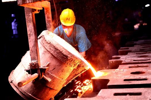
A line-frequency induction furnace in the strict sense has no inverter — the mains feeds the coil through a step-down transformer and a balancing capacitor bank, and frequency is therefore fixed at 50 Hz or 60 Hz. The MW-class mains-frequency coreless furnace in steel plants and the 50/60 Hz channel-type holding furnace in copper and brass mills are the canonical examples [S2][S3].
An MF unit, by contrast, rectifies three-phase mains to a DC bus and inverts it through an IGBT or SCR stack — exactly the converter architecture documented in the VFD (variable frequency drive) reference page — with a capacitor–inductor resonant tank matching the coil. The GWG-J "1000 Hz" model takes 380 V or 690 V 6-pulse AC, rectifies to a 500 V or 880 V DC bus, and inverts at the rated 500/1000 Hz to drive the induction coil at 1500 V or 2600 V or 3400 V depending on capacity [S1]. That shared rectifier + inverter + resonant-tank topology is the same pattern covered in the line-frequency furnace entry and the general induction furnace entry in the encyclopedia, and it is why a process engineer specifying a furnace also has to specify the VFD and its cooling, harmonic-mitigation and protection envelope as a coupled subsystem rather than as a separate purchase.
Selection Criteria: Which Class for Which Duty
Four decision criteria separate coreless-line-frequency, coreless-MF, and channel-line-frequency in practice: (1) batch vs continuous duty, (2) melt-down vs hold-only vs duplex, (3) metal family and melt cleanliness, and (4) minimum economical capacity. Coreless-line-frequency wins for steel-mill primary melting above ~5 t per furnace, coreless-MF wins for foundry batch melting from 0.5 t to 5 t, and channel-line-frequency wins for holding of copper, brass, zinc, aluminium and cast iron where the bath never goes empty [S1][S3]. The IAS Copper product list explicitly includes both channel and crucible variants, with a dedicated "Holding Furnace" and "Horizontal Continuous Casting Furnace" sub-class — a taxonomy the induction furnace encyclopedia page generalises across all metals [S3].
Coreless furnaces are the right answer when the operation is batch, cold-start, multi-alloy, or requires fast alloy-changeover (lift-swung coil, dump the heel). Channel furnaces are the wrong answer in those cases because the molten heel traps 30–60% of bath volume, contaminates alloy switches, and cannot be drained for refractory repair. The casting-ladle type map downstream of the furnace uses coreless tilting pour for batch steel and channel-overflow or pump pour for continuous casting, which is consistent with the upstream selection rule above.
Sub-Variants: Vacuum, Drum, Compact, R&D
Beyond the main classes, the IAS catalogue documents sub-variants that matter for spec engineers: vacuum melting furnaces for steel and copper, drum-type induction furnaces for copper, horizontal continuous casting furnaces for copper and brass, compact crucible systems for cast iron and steel (R&D-grade), and tank-melting furnaces with crucible inductors for aluminium [S3]. Each sub-variant inherits the parent class's power topology (line-frequency transformer-fed, or MF/HF inverter-fed) and adds a process vessel — vacuum chamber, drum shell, casting tundish, or sealed tank.
The converter section of the same vendor product list splits the electronics side into "Direct converter" and "Oscillating circuit converter" — terminology that maps directly onto line-frequency (direct, mains-fed) versus MF/HF (oscillating, inverter-fed) architectures [S3]. The "Oscillating Circuit Converter" name is functionally equivalent to the static-frequency-converter stack inside an induction furnace, i.e. a rectifier + inverter + capacitor–inductor tank driving the coil at a non-mains frequency.
Limitations, Failure Modes and Sourcing Notes
Mains-frequency coreless furnaces suffer low power density and poor melt efficiency on small baths (sub-1 t), which is why the GWG-J product line steps from 1000 Hz (0.5–1 t) to 500 Hz (1.5–8 t) as capacity rises [S1]. Channel furnaces suffer heel-freeze risk on power interruption, inductor refractory life is the limiting maintenance interval, and the molten heel must be kept molten 24/7 in continuous operations [S3]. The 10–20% energy-saving claim on the GWG-J control platform is specifically against "domestic traditional machines of the type", not against a generic baseline, so the spec engineer should treat it as a within-class delta, not a market-wide average [S1].
For sourcing, Okorder lists 25–120 day delivery on plywood-case packaged MF coreless units with TT or LC payment, FOB Qingdao; a comparable channel-type unit ships direct from OEM in Iserlohn [S1][S3]. The automatic molding line and molding line downstream of a foundry furnace will set the throughput target the furnace capacity must match, and the conveyor sorting line upstream sets the charge-material feed rate. Specifying a line-frequency furnace and its paired VFD as one coupled subsystem is the cheapest way to avoid the most common commissioning failure: an inverter-sized coil on a mains-rated cooling skid (or vice versa).