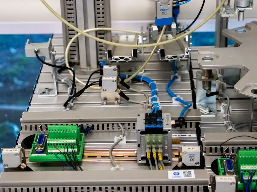
A linear module is a ready-to-install single-axis motion unit combining a profile, a guided bearing system, and an integrated drive, sized by payload, stroke, speed, and required positioning accuracy before any motor or controller is selected [S1].
For material handling, the engineering priority is moving mass over a defined stroke at a defined cycle rate, not the sub-micron accuracy a semiconductor stage demands, so the selection tree is dominated by drive type and supported-versus-unsupported mounting rather than by encoder resolution [S1][S2].
Four Drive Technologies Define the Material-Handling Decision
Ball-screw, timing-belt, rack-and-pinion, and linear-motor drives cover the vast majority of linear motion applications, with each technology occupying a distinct payload-versus-speed envelope [S8]. Ball-screw modules typically deliver the highest positioning accuracy and repeatability in the sub-100 mm/s range, while timing-belt modules extend stroke length economically into the 1–6 m range commonly seen in packaging and pallet transfer [S8]. Rack-and-pinion modules are specified for long-stroke, high-payload handling (often above 100 kg per axis) where a belt would stretch, and linear-motor modules are reserved for high-acceleration, maintenance-light cycles where the cost premium is justified by throughput [S8]. The full engineering decision tree is captured in our linear module reference page.
Load, Stroke, and Moving Mass: The First Three Calculations
Selection professionals evaluate mechanical load, stroke length, motion profile, and positioning accuracy as a connected sequence rather than independent parameters, because moving mass and required acceleration together set the drive torque, which in turn limits the usable ball-screw lead or belt width [S1][S5]. Engineers therefore calculate total moving mass (payload plus carriage plus any gripper or fixture), then derive peak speed and acceleration from the cycle-time target, before touching a catalog number [S1]. Stroke is set by the longer of the two end positions plus a safety margin, typically 10–50 mm at each end depending on deceleration strategy, to prevent mechanical crash on servo fault [S1]. A 12-step process of defining the application, calculating the mass, selecting the drive, and verifying safety factors is the published industry workflow [S1].
Supported, Cantilever, and Vertical: Mounting Geometry Drives the Bearing Choice

Linear modules are often not fully supported along their length but are installed as unsupported structures, with the system left unsupported or supported at several discrete points along the stroke [S4]. This is the most consequential decision in a handling project, because an unsupported long stroke requires a rigid profile and a high-moment bearing arrangement, otherwise the carriage will bind and repeatability will drift within weeks of commissioning [S1][S4]. Mounting orientation (horizontal, wall-mount, vertical Z-axis) changes the effective load on the bearing and the hold-brake requirement on the motor, which is why Bosch Rexroth's selection tooling flags orientation before speed or precision [S5]. Vertical Z axes handling payloads above a few kilograms must use a back-driven-resistant drive (typically ball screw with a fail-safe brake, or a non-back-drivable rack) to prevent drop on power loss [S1].
Aluminum Versus Steel Housings, and the Lubrication Reality
Aluminum extruded housings dominate the standard-duty market because the profile can be cost-effectively sized to a wide range of stroke lengths, while steel housings are reserved for heavy-payload or high-rigidity handling modules where deflection would limit cycle life [S2]. Housing material directly governs long-term accuracy and repeatability because thermal expansion, stiffness, and damping all differ between the two, with steel generally holding accuracy better over a 24-hour production shift [S2]. Lubrication is the field reality that selection guides must acknowledge: even a perfectly specified module loses its precision envelope within months if the grease interval is ignored, and precision modules are typically specified with centralized lubrication blocks or factory-prelubricated slide units to extend service intervals [S2]. For material handling in washdown or food-grade environments, the housing, seals, and bearing lubricant must be specified together, which is the central trade-off in any food-grade linear module selection.
Gantry, XY, and Cross-Cantilever Configurations in Material Handling
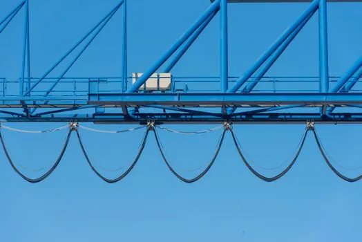
Linear modules can be combined into XVz gantries, I-beam modules, XY stages, and cross-cantilever modules, and these multi-axis assemblies dominate the handling machine market because they extend a single-axis reach into a working envelope [S3]. Horizontal handling uses XY stages to transfer items between two stations, vertical handling uses Z-axis modules to lift and place, and mixed XVz gantries are the standard pick-and-place architecture for palletizing, machine tending, and battery cell stacking [S3]. Material-handling OEMs typically configure the module count, stroke, and drive to customer cycle-time and payload requirements rather than to a standard catalog model, which is why a selection discussion that stops at a single axis misses most of the engineering value [S3]. The handling-specific decision points (load on the unsupported axis, Z-axis hold-brake, and gripper mass included in moving-mass calc) are detailed in the material handling reference.
Selection Criteria Comparison: Four Drive Types Side by Side
The four drive technologies map onto a decision matrix that an engineer can use directly. Ball-screw modules offer the best positioning accuracy (typically ±0.01 mm) and high thrust, but limited stroke length and lower maximum speed than belt or rack drives. Timing-belt modules cover the longest strokes (commonly 1–6 m) at moderate speed and accuracy, with low cost per meter of stroke, and are the default for cross-belt transfers and packaging pick-and-place. Rack-and-pinion modules carry the highest payloads and tolerate harsh environments, with stroke limited only by the rack length, and they are standard for heavy-pallet handling and machine-tending Z axes. Linear-motor modules deliver the highest acceleration and zero mechanical wear on the drive element, at a 2–4× cost premium and reduced thrust density per unit volume, and are specified for high-throughput electronics and battery cell handling [S1][S8]. The complete decision tree is anchored in the linear actuator reference and the linear bearing encyclopedia page for the matching bearing block.
Motor Coupling, Safety Factors, and the Spec Sheet Closing Items
Linear modules can be configured with direct motor mounting, planetary gearbox mounting, or belt-pulley mounting, and the choice is set by the required torque and speed window rather than by the motor itself [S7]. Direct-mount servo coupling is preferred for high-dynamic applications because it eliminates backlash from a gearbox; planetary gearboxes are inserted where a small motor must drive a high-inertia load; and belt-pulley coupling is the cost-effective path for low-duty horizontal strokes [S7]. The final steps of any serious selection are: verify the safety factor on peak load (industry default is 1.5–2.0× for handling, 2.0–3.0× for vertical axes with human-accessible envelopes), confirm the lubrication interval matches the maintenance schedule, and check the encoder feedback resolution against the required positioning tolerance [S1][S5]. Future expansion is a real line item: selecting a profile size one step above the calculated minimum often saves a full re-design when the next product variant adds a 20% payload [S1].
Track these two engineering signals over the next planning cycle: first, the growing share of linear-motor modules in mid-payload handling (10–50 kg) as servo and magnet costs fall, and second, the migration of safety-factor conventions toward machine-risk-category-based selection per ISO 13849-1, which increasingly replaces the older "1.5× and forget" rule that older selection guides still print.