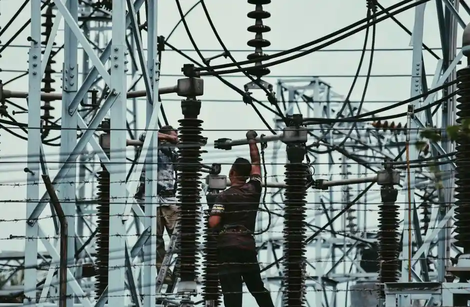
A load-break switch (LBS) is rated to make and break normal load current and limited overloads, typically up to 3-4x its rated current In, but it has no short-circuit breaking capacity, only a short-circuit making capacity Icm, per IEC 60947-3 for low-voltage units and IEC 62271-103 for units rated up to 52 kV [S4][S3].
The practical envelope sits between a no-load isolator and a full circuit breaker: an LBS can carry and switch its continuous thermal current Ie, can close onto a peak fault current without welding the contacts, and can hold a defined short-time withstand current Icw for 1 s or 3 s while closed, but it cannot open a bolted fault [S4][S1]. For distribution builds through 33 kV, that boundary is exactly why LBS units paired with current-limiting fuses are replacing more expensive circuit breakers in loop and radial feeders [S3].
Definition and Scope Under the Governing Standards
The breaking capacity of an LBS is defined as the current it can interrupt at system voltage and normal-load power factor, equal to its continuous rated current, plus limited inductive and capacitive currents for switching unloaded transformers, cables, and overhead lines [S3][S1]. Per IEC 62271-103, LBS units with rated voltages up to 52 kV must demonstrate this capability through prescribed test duties, including a short-circuit making test on the contacts [S3].
Under IEC 60947-3 (LV), an LBS is explicitly a switch with a making capacity, not a protective device: it may be assigned Icm (short-circuit making capacity) but not a short-circuit breaking capacity, and opening it under a fault is treated as a misuse that produces sustained arcing [S4]. In North America the equivalent performance language is carried in IEEE C37.71 and ANSI C37.72 for load-interrupter switches [S4].
Making Capacity (Icm) vs Breaking Capacity: the Distinction That Kills Specs
Making capacity is the peak fault current the LBS can successfully close onto without welding the main contacts; it is electrodynamic and thermal in nature, driven by the first half-cycle peak of the prospective fault current [S4]. Breaking capacity is the current the device can safely part and extinguish; for an LBS that envelope stops at normal load current and a defined overload band, generally 3-4x In, beyond which the arc plasma cannot be deionized inside the quenching chamber [S4][S5].
Concretely, a 630 A, 12 kV indoor LBS is type-tested at 200 A, 400 A, and 630 A continuous ratings against IEC 62271-103 breaking duties, and its Icm is declared separately as a peak kA value at the same voltage [S3][S6]. Mistaking Icm for an interrupting rating is the most common specification error: a 630 A LBS with Icm = 63 kA peak can close onto a 25 kA rms bolted fault, but it cannot open that fault, and the upstream protective device must clear it within the LBS's Icw time [S4].
Four Operating Boundaries an LBS Must Satisfy
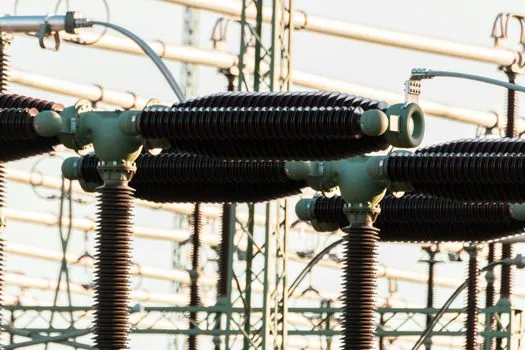
IEC 62271-103 and IEC 60947-3 each require the LBS to demonstrate four functional capabilities, and each one maps to a declared rating on the nameplate [S3][S1].
First, it must interrupt a current equal to its continuous rated current at system voltage and normal power factor, the basic breaking duty. Second, it must provide sufficient dielectric strength to isolate the circuit in the closed position, verified by power-frequency and impulse withstand tests. Fourth, it must carry the maximum prospective fault current for the duration required for the series protective device (fuse or breaker) to clear the fault, expressed as Icw at 1 s or 3 s [S3][S1][S4].
How Quenching Medium Sets the Making and Breaking Envelope
The arc-extinguishing medium defines the upper end of the breaking envelope and the mechanical complexity of the unit [S5]. Solid gas-producing LBS designs use arc-energy-decomposed material in the chute to blow out the arc, simple in construction and used at voltage levels up to and including 35 kV. Puffer-type LBS units use a piston driven by the opening mechanism to compress a gas column across the arc, also typically applied up to 35 kV. Compressed-air LBS units use externally supplied air and are applied at 60 kV and above where higher interrupting duty is needed. SF6 gas LBS units use sulfur hexafluoride for its high dielectric strength and arc-quenching performance, and vacuum LBS units use a sealed vacuum interrupter bottle, both of which are the dominant choices at 12-36 kV indoor and outdoor ratings [S5].
For a load switch selection in 2026, the practical differentiator is not nominal voltage but the declared making-capacity Icm, the short-time withstand Icw (1 s or 3 s), the mechanical endurance (commonly under 5,000 operations), and the electrical endurance (under 1,000 operations at rated current) [S4]. Specifiers should treat any Icm value without a paired Icw as incomplete, because the Icw defines how long the closed contacts survive while the fuse or breaker clears the fault the LBS just made onto [S4].
Pass Criteria After the Type-Test Sequence
IEC 62271-103 sets a quantitative pass bar after the breaking and short-circuit making test sequence, and that bar is the operational yardstick most buyers miss [S3]. After the test duty TDma, the mechanical function of the switch and its insulators must remain in essentially the same condition as before the test. Compliance with "able to carry its rated normal current" is judged by one of three conditions: visual inspection of the primary contacts shows good condition; or, where impractical, the measured contact resistance does not increase by more than 20% compared to the pre-test value (up to 10 no-load operations are permitted before the measurement); or, if those checks are inconclusive, testing at rated thermal current shows no thermal runaway and no temperature or temperature-rise limit is exceeded [S3].
A 20% contact-resistance rise after a making test is the most useful field proxy: above that, the contact has micro-welded and the Icm rating is effectively derated, even if the visual check passes [S3]. This is the same boundary that separates an LBS from a fire-rated door class of equipment in another domain, both are about declared rating versus actual post-test condition under a written standard.
LBS vs Circuit Breaker: Decision Criteria on One Page
The decision between an LBS (with fuses) and a full circuit breaker comes down to four criteria: fault-clearing duty, endurance, coordination complexity, and cost per switchbay [S2][S4][S7].
On fault-clearing duty, an LBS paired with current-limiting fuses can clear high fault currents because the fuse operates; the LBS itself only makes and breaks load and limited overload, while the circuit breaker detects and interrupts faults up to its Icu/Ics rating [S2][S4]. On endurance, an LBS is typically rated for under 5,000 mechanical and under 1,000 electrical operations, well below a circuit breaker's 10,000-cycle class, so high-cycle automated switching favors the breaker [S4]. On coordination, an LBS-fuse combination gives simple, low-cost overcurrent protection with clear let-through characteristics, while a circuit breaker offers adjustable trip curves, reclosing, and remote telemetry but at higher unit cost and bay complexity [S7]. On cost, an LBS switchbay at 12-36 kV is materially cheaper than an equivalent breaker bay, which is the economic driver behind the LBS-with-fuse pattern in 33 kV distribution feeders [S3][S2].
Selection Rules, Misuse Patterns, and 2026 Sourcing Signals
Specify an LBS when the application is infrequent load switching, transformer primary isolation, or ring-main sectionalizing, and the fault protection is delegated to upstream or series fuses; do not specify an LBS where the device itself must clear a bolted fault [S4][S7]. For electronic load test benches and checking-and-testing apparatus bays, the same rule applies: the LBS makes and breaks the test setup under load, but fault protection rides on the upstream breaker or the test set's own protection.
On sourcing, the verifiable signal to track into Q4 2026 is the 52 kV upper bound in IEC 62271-103, which still defines the test regime for HV LBS, and the convergence on SF6-free and vacuum quenching at 12-36 kV driven by SF6 regulatory phase-down; manufacturers publishing an Icm in kA peak plus an Icw at 1 s and 3 s on the same nameplate line are the ones whose type-test reports will line up with the IEC clauses specifiers actually audit. A practical next read for transformer-primary applications is the 2026 spec and sourcing guide for Load Break Switch for Transformer Primary Disconnect, which extends the same IEC envelope into transformer isolation duty.