
A luffing jib tower crane keeps the working footprint small by raising its main jib above the counter-jib instead of swinging a long horizontal arm, so its slewing (tail-swing) radius is typically about half that of a hammerhead crane of similar capacity [S2][S3]. A hammerhead tower crane, by contrast, uses a fixed horizontal jib and a long counter-jib carrying counterweight slabs to balance the load across a maximum working radius, which is why it remains the reach workhorse on open sites [S2][S4].
On a 55–60 m radius hammerhead build, the jib above the slewing platform is essentially the full reach plus a counter-jib that can extend 15–20 m behind the tower, and that envelope must be kept clear of neighbouring structures, roads, and overhead lines [S2]. On a luffing jib of the same class, the main jib can be raised 15–75° from horizontal depending on model, and the counter-jib is short (often 5–8 m) because the luffing motion itself absorbs part of the overturning moment [S3][S5]. That geometry is the reason the same site plan that rejects a hammerhead will accept a luffing jib crane.
Counter-Jib Geometry and the Slewing Footprint
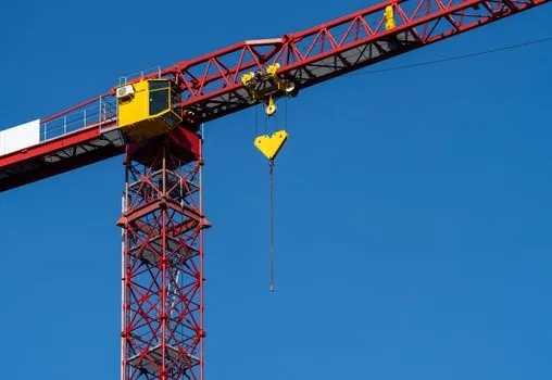
The hammerhead silhouette is a "T" because the jib and the counter-jib are roughly mirror images in length, and both project horizontally from the slewing table on top of the tower [S4]. A typical 12–18 t hammerhead carries a counter-jib of 12–18 m loaded with concrete or steel slabs whose total mass is matched to the maximum moment at the jib's farthest working radius, which is why hammerhead load charts hold tip capacity almost flat across most of the jib [S2].
The luffing jib replaces that long counterweight arm with a short rear platform and a luffing cylinder (or rope-reeving system) that pulls the main jib up and down, so the crane's centre of mass stays close to the tower axis [S1][S3]. Operators therefore work with a slewing radius that is commonly 4–6 m on a luffing jib versus 14–20 m on a hammerhead of similar maximum capacity, and that delta is what lets a luffing jib sit in a 12 × 12 m inner-city site footprint [S3].
Working Radius: Where Each Crane Wins and Loses
A hammerhead's fixed horizontal jib gives the longest working radius in the tower-crane family, with common production models reaching 55–80 m on a single jib and more on jib-extension configurations [S2][S4]. Because the radius is set by the trolley position rather than by the jib angle, tip-load curves on hammerheads are stable: at 30 m the crane may lift 8–12 t, and at 60 m it may still lift 2.5–4 t, which keeps hoist cycles predictable for rebar, formwork, and steel picks on a big footprint [S2].
A luffing jib's working radius is a function of the jib angle, so radius and height are traded continuously during the lift. At a low angle (jib near horizontal) the reach is maximum and tip load is lowest; at a steep angle the reach shortens but capacity rises, and the same load chart has to be re-read for every set position [S1][S3]. In the listed self-erecting reference equipment, a Liebherr 81 K posts a max radius of 148 ft (about 45 m) with 2,976 lb (about 1.35 t) at the tip and 13,227 lb (6 t) at 29 ft (about 8.8 m), a radius-to-tip-load shape that mirrors how every luffing jib chart slopes [S5].
Airspace, Overhead Lines, and Multi-Crane Plans
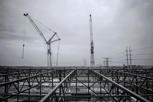
The defining reason to choose a luffing jib on a tight site is airspace: the main jib can be raised high enough to clear an adjacent building, a hospital helipad corridor, or a live overhead transmission line, and the short counter-jib keeps the tail from sweeping over a neighbouring property line or a public road [S2][S3][S4]. On a 4- to 5-tower shared-airspace high-rise, planners usually specify luffers or flat tops precisely to keep jib heights staggered and counter-jibs inside the site boundary [S2][S3].
Hammerheads, with their full-length horizontal jib and a counter-jib of similar mass, are unsuitable where any structure, crane, or wire is in the jib plane above the slewing circle, and that is why industry guides pair them with "open sites with room to operate" rather than congested cores [S2][S4]. The same guides recommend luffing jib and flat top for tight urban sites and for any plan where multiple cranes must overlap jib arcs without colliding [S2].
Capacity, Cycle Time, and Operating Cost
Per unit of structural steel, luffing jibs cost more than hammerheads because of the luffing mechanism, the heavier tower top, and the more involved assembly, and that higher capital cost is the consistent caveat in selection guides [S3][S4]. Hammerheads are described as "often more budget-friendly" and as the "workhorse" choice when no site constraint pushes the buyer toward a luffing jib [S2][S3].
Cycle time also diverges. A hammerhead trolley runs out and back along a fixed jib, so the hoist line only raises and lowers; a luffing jib has to luff the jib to change radius on every reposition, which adds a second motion to each cycle and slows the crane during multi-pick precast or rebar days [S3][S4]. On heavy steel erection, where every pick is a single high-capacity lift, the luffing jib regains the advantage because its steep-angle capacity outclasses a hammerhead at the same radius, and the operator can stand the jib up out of the way between picks [S3].
Selection Matrix: Decision Criteria Side by Side
The four criteria that drive the luffing-vs-hammerhead call, lined up against published guidance, are: site footprint (counter-jib + slewing radius), working radius envelope, airspace clearance, and tip-load stability across the radius. On a 1–10 scoring weight, hammerhead wins on working radius and tip-load flatness, luffing jib wins on footprint and airspace, and the two tie on capacity class for the same mast size [S2][S3][S4].
Concretely: for an open suburban plot with a single 60 × 40 m building footprint, a hammerhead on a 50–60 m jib with a 14–18 m counter-jib fits and lifts more per hour at lower rental cost [S2][S4]. For a 25 × 25 m inner-city plot hemmed in by 30 m neighbouring buildings and a 110 kV line 18 m above ground, a luffing jib with a 5–8 m counter-jib and a 40–45 m variable-angle jib is the only configuration that both lifts to the top floor and stays inside the airspace envelope [S1][S3]. A flat top sits between those two and is the right answer when the site is open but two or more cranes must share jib airspace without the counter-jib interference a hammerhead tail brings [S2][S3].
Spec Boundaries and Common Failure Modes
The two most common spec errors on luffing jibs are under-allowing for counter-jib clearance in the site plan and over-promising tip load at low jib angles; the most common on hammerheads are under-allowing for the full counter-jib swing arc and misreading the load chart at maximum radius with multiple reeving parts [S3][S5]. Both errors collapse onto the same fix: pull the manufacturer's load chart for the exact jib length, exact counter-jib configuration, and exact reeving, then draw the working radius envelope on the site plan before foundation design [S3][S5].
For background on how slewing radius and counter-jib envelope interact with site geometry, the tower crane category overview ties the same slewing-radius discussion to flat top and self-erecting variants; for comparison with mobile crane envelopes on shared sites, see crawler crane vs mobile crane footprint notes and mobile crane footprint reference; for warehouse / port applications where the same counter-jib-vs-tail-swing logic drives the gantry choice, see gantry crane envelope and rail gauge. For automated-storage equivalents where a similar short-tail envelope matters, the stacker crane aisle-length comparison is the closest spec-side analogue.
Two trackable signals to watch on the next tender: OEM load-chart revisions that add a low-angle tip-load derate of 10–20% on luffing jibs (already standard on Liebherr and Potain high-capacity luffers), and a growing number of urban jobs requiring a written "no counter-jib swing over property line" clause, which forces a luffing jib or flat top specification regardless of cost [S3][S4].
This topic is covered further in Rebar Pricing: $/cwt vs $/ton vs $/piece Compared.