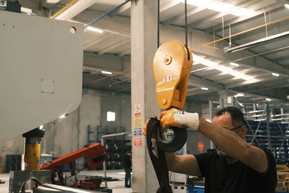
Medium-tonnage die casting cells, generally 400 to 800 metric tons of clamping force, require 5 to 8 m of clear overhead crane hook travel and 25 to 40 m² of cleared floor footprint per machine when die change motion is included, and these two envelope numbers govern whether a quick die change retrofit will fit a given bay [S1][S2].
Shibaura Machine supplies horizontal cold chamber die casting machines from 135 to 3500 metric tons, and the mid-range models in that catalogue are the most common platform specified for automotive structural components and electronics housings [S2]. Walker Die Casting operates 38 horizontal high pressure die cast machines spanning 1000 to 4500 tons, which is a useful upper-anchor when sizing the layout of a multi-machine cell [S7]. The NADCA Product Specification Standards for Die Castings (1994 baseline) and the NADCA Product Design for Die Casting sourcebook remain the most-cited reference documents for platen, die, and clearance geometry in North American plants [S3][S6].
Footprint by Clamping Force Tier
Footprint scales with clamping force because platen size, tie-bar span, and shot-end reservoir volume all grow together. A 400-ton horizontal cold chamber machine typically occupies 18 to 25 m² of machine footprint, an 800-ton unit 25 to 35 m², and a 1600-ton unit 35 to 50 m², before any die change clearance is added [S2][S7].
For die change operations the floor must clear an additional 6 to 12 m² around the moving platen so that a die cart, roller track, or die lifter can park the outgoing die set without crossing the operator path [S1]. The fixed platen side requires roughly 1.5 to 2 m of rear clearance for hydraulic quick clamp manifolds, cooling hose reels, and the sprue cutter exhaust [S8]. Total cleared bay footprint for a 600-ton cell with full quick die change provisions, including die cart parking and utility trenches, sits in the 30 to 45 m² band that most plant layouts budget per machine [S1].
Crane Hook Height and Vertical Clearance
Crane hook height is the most often undersized parameter in a green-field die casting bay, because the required clearance stacks: machine platen opening stroke, die set height, sling height, and a 0.5 to 1.0 m safety margin between the hook and the die lift point [S1][S2].
For a 400-ton machine the platen opening stroke is typically 400 to 600 mm, die set height 500 to 800 mm, sling 1.0 to 1.5 m, and the safety margin 0.5 m, which sums to a minimum hook height of 2.5 to 3.5 m above the floor when the platen is fully open [S1]. For an 800-ton unit the comparable stack is 600 to 1000 mm stroke, 700 to 1100 mm die height, 1.5 to 2.0 m sling, and 0.5 m margin, which gives 3.5 to 4.5 m. Industrial surveys of medium-tonnage cells place the working hook-height range at 5 to 8 m so the operator can also lift a die vertically off the die cart before swinging it into the machine, and so the same crane can service a furnace ladle without repositioning [S2].
The Shibaura medium-tier portfolio uses servo-hydraulic injection and platen geometries consistent with this 5 to 8 m hook-height range, which is why most North American automotive Tier-1 cells standardize on 6 to 7 m of under-hook clearance for the 400 to 800 ton class [S2].
Matching Die Weight to Handling Equipment
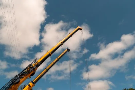
Quick die change retrofits fail most often because the die weight sits at or above the limit of the existing crane or die lifter, and the system is selected on clamp force alone rather than on the die weight band that actually runs on the machine [S1].
For a 400-ton cell the typical die set weighs 1500 to 3500 kg, for an 800-ton cell 3500 to 7000 kg, and for a 1600-ton cell 7000 to 12000 kg, and these are the values that should drive the crane and die cart selection [S1][S2]. A die whose center of gravity is offset by slides, slides, or unbalanced cooling stacks will swing unpredictably on a standard sling, and the quick change package must include a level-lift crossbar or adjustable sling bridle, not just stronger clamps [S1].
Die weight also drives rail height and roller track pitch. A die under 3000 kg can move on standard 50 mm pitch rollers with a manual die cart, while a die over 5000 kg needs powered rollers, a 75 to 100 mm pitch track, and a die cart rated for the maximum weight in the family, not the average [S1].
Platen, T-Slot, and Hydraulic Clamp Geometry
Platen size, T-slot position, mounting holes, tie-bar clearance, and prior wear all determine whether a hydraulic quick clamp will actually seat, and the catalog clamp force number is meaningless if the clamp body cannot fit around the ejector rods, cooling manifolds, and die protection plates [S1].
Measure the usable clamping edge on both fixed and moving platens before any quick change equipment is ordered, and inspect for previous modifications that have reduced available space [S1]. For medium-tonnage machines, platen width is typically 800 to 1100 mm and height 900 to 1300 mm, with T-slots in the 20 to 30 mm range and 100 to 150 mm center spacing [S8]. The standard die casting machine parameters table lists a typical pressure chamber flange diameter around 110 mm and a location ring height near 10 mm, which sets the geometric baseline for locating the die before clamps engage [S8].
If the die base changes between tooling families, the plant should adopt a standard clamping rule before installation; without it operators adjust clamp positions differently on each shift and the quick change system becomes a slow change system with extra parts [S1].
Layout Pattern: Cell vs Linear Bay

Medium-tonnage die casting machines are commonly installed in either a transverse cell layout, where the die moves in and out perpendicular to the platen, or a linear bay layout, where the die moves parallel to the platen along a roller track that runs the length of the bay [S1].
The transverse cell is more compact, typically 25 to 30 m² for a 600-ton machine including die change clearance, and works well for high-mix production with frequent die changes [S1]. The linear bay consumes 35 to 45 m² per machine but allows the same crane and roller track to service multiple machines, which is the pattern seen in Walker Die Casting's 38-machine plant and in most contract caster facilities with 4 or more units [S7]. Kurt Die Casting's equipment list, which pairs 600-ton and 630-ton work centers with auto spray and auto ladle, is a representative snapshot of the medium-tonnage cell configuration in current North American service [S9].
For high-mix quick-change work the transverse cell wins on changeover time, and for high-volume dedicated work the linear bay wins on crane and floor utilization, so the choice is driven by product mix, not by the machine itself [S1].
Utility Connections and Quick Disconnect Stacks
Every quick die change retrofit adds quick-disconnect stacks for hydraulic, cooling water, lubrication, and die-spray, and these stacks have a vertical and lateral envelope that competes with the crane hook path [S1].
Medium-tonnage dies typically carry 4 to 8 cooling water circuits, 2 to 4 hydraulic core-pull lines, 1 to 2 lubrication lines, and 1 to 2 die-spray lines, each terminating in a multi-port manifold mounted on the fixed platen or on a swing arm above the die space [S1]. The manifold stack adds 300 to 500 mm of vertical envelope and 200 to 400 mm of lateral envelope on each side of the die, which must be subtracted from the effective crane hook height or the manifold must be mounted on a swing arm that retracts during die change [S1][S8].
NADCA's design sourcebook recommends routing utility drops from overhead rather than from the floor wherever the crane is the primary die handling method, because floor trenches force the die cart to cross flexible hose bridges and slow the change [S3]. Plants that ignore this end up with 8 to 12 minutes of manual hose work on every die change, which negates the rest of the quick change investment [S1].
Safety, Standards, and Sourcing
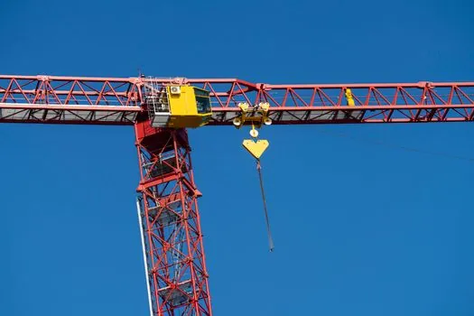
Die change is a high-energy operation involving suspended loads, hot dies, and high-pressure hydraulic clamps, and the layout must satisfy OSHA 29 CFR 1910.179 overhead crane rules and ANSI B30.9 sling rules, which set the 0.5 m minimum safety margin between hook and lift point used in the vertical clearance calculation above [S1].
NADCA Product Specification Standards for Die Castings and the NADCA Product Design for Die Casting sourcebook (2015 seventh edition) remain the governing reference documents for die geometry, tolerances, and mounting practice in North American plants [S3][S6]. For aluminum and zinc alloys, NADCA-cited standard production tolerances are typically ±0.002 in for aluminum and ±0.0005 in for zinc, which set the precision baseline that the die change system must preserve by repeatable die seating [S4]. Designers and specifiers should cross-check platen, T-slot, and hydraulic clamp geometry against the NADCA standards before finalizing any quick die change retrofit [S6].
Two trackable signals through Q4 2026: Shibaura Machine's North American parts and service operation in Elk Grove Village, IL, has been actively publishing medium-tier machine updates since the Toshiba rebrand, which is a useful channel for confirming platen and clearance data on specific 400 to 800 ton models [S2]. The Kinghou quick die change article (published 2026-07-03) is the most current consolidated checklist for retrofitting existing medium-tonnage cells without replacing the crane or the bay floor [S1].
For related reading on how die change decisions interact with downstream process choices, see this comparison of manual vs semi-automatic gravity die casting machine cost and this look at stud weld vs drilled and tapped hole strength trade-offs where similar quick-change logic applies to fastener and joint specification.
Component reference pages worth checking: die casting machine, aluminum die casting machine, and gravity die casting machine.