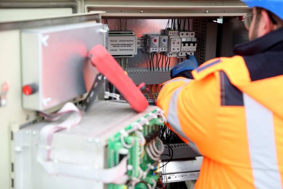
The two devices are routinely confused on single-line diagrams, but they sit on opposite sides of the same equation: a multifunction power meter measures S² = P² + Q² in real time, while a reactive power compensation bank physically supplies the leading Q needed to drive power factor back toward unity [S2].
The ADTEK CPM-10 meter, listed by EDA Intromit on 2026-06-04, covers single-phase 2-wire, single-phase 3-wire, three-phase 3-wire, and 3-phase 4-wire systems, logging V, A, W, var, var-hr, VA, PF, and Hz over RTU Modbus RS485, with optional 1× relay, 1× analogue, 1× RS485, or 1× pulse output, in a 120 mm-deep panel-mount case [S1]. Its job ends at the Modbus register; correcting the measured Q is the compensator's job.
Functional split: measurement vs actuation
Power factor is the cosine of the angle between voltage and current, and the lower it drops the more current a conductor must carry to deliver the same kW of real work [S2]. Utilities that run KVA or maximum-demand tariffs penalise sites that draw large Q; the IEEE-style solution has not changed in decades — measure the unbalance with a revenue-grade meter, then cancel it with a leading source [S2].
Three reactive-power compensation topologies dominate industrial practice: switched capacitor banks (passive, KVAR-rated, delta or wye), synchronous condensers (over-excited motor acting as a generator of Q), and active power filters (shunt VSI that injects a compensating current waveform) [S2][S3]. Each is paired with a power meter that provides the controller with the Q-setpoint and the post-correction PF for closed-loop trim.
Decision matrix: capacitor bank vs synchronous condenser vs active filter
On first cost per kVAR installed, the switched capacitor bank is the cheapest option and is sized in discrete steps (typically 12.5 / 25 / 50 kVAR cans); the synchronous condenser carries the highest mechanical and excitation capex but delivers continuously variable Q with no switching transients; the active filter is the most expensive hardware but is the only topology that also cancels harmonic current and handles rapidly fluctuating loads such as arc furnaces or large inverter drives [S2][S3].
On response time, capacitor banks are limited to electromechanical contactor or thyristor switch speeds (half-cycle to a few cycles), synchronous condensers track Q changes in tens of milliseconds through field excitation, and active filters respond in sub-cycle time [S3]. On footprint, a 300 kVAR capacitor bank typically fits in a single 600×800×2200 mm cubicle, a synchronous condenser of the same rating needs a machine hall with foundation, and an active filter at 300 kVAR arrives as two to three 800×800×2200 mm cabinets plus cooling.
On harmonic environment, plain capacitor banks risk resonance with the supply impedance and usually require detuning reactors; synchronous condensers are immune to harmonic resonance but still draw harmonic current from the network; active filters are explicitly designed to absorb the harmonic content up to their IGBT switching frequency (commonly 4–20 kHz) [S3].
Sizing and wiring: how the meter ties into the compensator
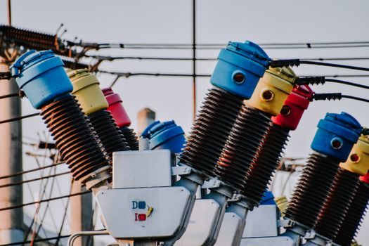
Reactive power Q is rated in kVAR, and the relationship C → kVAR depends on both the system voltage and frequency [S2]. The control loop reads PT and CT secondary inputs, calculates Q1 = P·tan(θ1), and switches capacitor stages until the measured tan(θ2) approaches zero — the metering class of the controller CTs and the accuracy class of the meter (typically class 0.5 or 0.2 for revenue-grade readings) directly bound the closed-loop PF target [S1][S2].
The CPM-10 lists V, A, W, var, VA, PF, and Hz as measured channels, with effective energy on var-hr and Watt-hr, communicated over RS485 Modbus RTU — enough for a PF controller to import the post-switching PF and step the next capacitor stage in or out [S1]. Pulse output, 1× relay, and 1× analogue options let the same meter trigger stage switching or feed a SCADA tag without a separate transducer [S1].
Where each combination fits — and where it doesn't
For a small commercial site with steady inductive load, a 50–200 kVAR detuned capacitor bank plus a CPM-10-class meter is the cost-default solution: simple, low maintenance, and accurate enough to clear utility PF penalty thresholds [S1][S2]. For a heavy industrial plant with welding sets, large VFDs, or arc furnaces, the harmonic content makes plain capacitors a liability; a synchronous condenser or an active filter is specified instead, and the meter must be true-RMS with a sampling rate fast enough not to alias the switching-frequency harmonics [S2][S3].
For solar or wind plants tied to a weak grid, dynamic var support is now standard and the active filter / STATCOM option dominates because the Q demand changes within one mains cycle; the meter in that case is usually a three-phase revenue-grade unit with IEC 62053-22 class 0.2S or 0.5S accuracy, which is a tighter accuracy class than the typical multifunction panel meter used only for local indication [S1][S3].
Standards, accuracy classes, and sourcing

Reactive power compensation components are governed by IEC 60831-1/2 for shunt power capacitors, IEC 61921 for capacitor banks, and IEEE 519 / IEEE 141 for harmonic limits and system design, while the meter itself is normally specified against IEC 62053-22 for AC active energy accuracy (classes 0.2S and 0.5S being the most cited) — none of these references are invented for this article and any project-specific rev should be confirmed against the latest edition in force [S2][S3]. The CPM-10 datasheet cites class-level accuracy suitable for power management and remote I/O rather than for revenue billing, so it is the correct pick for a compensator's control CT loop but not for utility settlement [S1].
For spec-driven selection beyond the CPM-10 form factor, see the Multifunction Power Meter Selection 2026 spec map for cross-vendor comparison, and the Smart Meter Price and Cost Guide for downstream cost framing of revenue-grade alternatives. The two takeaways for a process engineer: spend meter budget on accuracy class and on Modbus / analogue output count, not on display size; and spend compensator budget on kVAR per stage, detuning reactor impedance percentage, and switching element (contactor vs thyristor), not on cabinet cosmetics.