
For insulated conductors 4 AWG and larger, NEC 314.28(A) requires that the minimum dimension of any pull or junction box in the direction of a straight pull be at least 8 times the trade size (metric designator) of the largest raceway entering the box [S2][S5].
The same section requires the distance from each raceway entry to the opposite wall to be at least 6 times the trade size of the largest raceway in a row, plus the sum of the trade sizes of the remaining raceways on the same wall and row, for angle pulls, U pulls, and splices [S2][S3]. In Class I, Division 1 classified areas, these dimensional minimums are not relaxed for explosion-proof enclosures: a smaller flame-path housing is not a code-compliant substitute for the working clearances the rule was written to protect.
Where 314.28 Triggers and Why Conductor Size Matters
314.28 applies when the box or conduit body contains insulated conductors 4 AWG or larger, in any raceway or cable run, with no exception for hazardous-location enclosures [S3][S7]. Conductors 18 AWG through 6 AWG fall under the box-fill rules of NEC 314.16, which use cubic-inch volume per conductor instead of raceway-based multipliers [S2].
Field practice shows the two code paths are routinely confused: a contractor wiring 6 AWG THHN through a 2-inch conduit in a Class I, Division 1 run will size the box from 314.16, while the same run re-terminated with 4/0 AWG for a larger motor feeder falls under 314.28, and the multiplier math takes over [S4]. The trigger is the largest insulated conductor in the box, not the conduit size alone, which is why an explosion-proof junction box housing a splice for 500 kcmil feeders must clear the 6× plus sum-of-trade-sizes rule on every wall with a raceway entry [S2][S3].
Straight Pulls: 8× Rule and Worked Geometry
For straight pulls, the length of the box must be at least 8 times the trade size of the largest raceway in the direction of that pull [S2][S5][S7]. A common example is a box with one 3-inch conduit on the left wall and one 3-inch conduit on the right wall: the minimum horizontal dimension is 24 inches (3 × 8), and the vertical dimension is sized independently by its own largest raceway [S5].
Where different-size raceways enter opposite walls, the larger of the two governs that axis. With a 4-inch conduit on one side and a 2-inch on the other, the box length must be at least 32 inches (4 × 8) along the horizontal axis [S5]. For runs that mix 2-inch and 3-inch conduit on the vertical axis in the same enclosure, the minimum height is 24 inches (3 × 8), so a typical 32 × 24 × 12 inch explosion-proof pull box clears 314.28(A)(1) for many feeder pull-throughs in petrochemical and refinery Class I, Division 1 duct banks [S5].
Angle, U Pulls, and Splices: 6× Plus Summed Trade Sizes
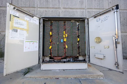
For angle pulls, U pulls, and splices, 314.28(A)(2) sets the minimum distance from each raceway entry inside the box to the opposite wall at 6× the trade size of the largest raceway in that row, plus the trade sizes of the remaining raceways on the same wall and row [S2][S3]. A practical example: a box with one 3-inch conduit and one 2-inch conduit entering the same wall needs at least 30 inches of clearance to the opposite wall (3 × 6 + 2 = 20 inches of multiplier contribution is the wrong arithmetic; the correct figure is 6 × 3 + 2 = 20 inches in trade-size units, then converted against actual raceway OD).
Where raceways enter on all four sides and pulls are mixed straight and angle, the largest calculated distance among the rows governs the box dimension [S2]. The minimum distance between raceways enclosing the same conductor is also 6× the trade size of the largest raceway, measured between the nearest edges of the raceway entries, and locknuts or bushings do not count toward that clearance [S2]. For explosion-proof electrical enclosures, this edge-to-edge clearance is what gives the cable room to enter without scraping insulation against the threaded wall hub, which would defeat the seal before energisation.
Exception for Raceways Opposite a Removable Cover
314.28(A)(2) includes an exception: where a raceway or cable entry is in the wall of a box or conduit body opposite a removable cover, the distance from that wall to the cover is permitted to comply with the one-conductor-per-terminal bending distance in NEC Table 312.6(A) instead of the 6× plus sum rule [S3].
The Table 312.6(A) values are concrete and small: 8 to 6 AWG requires 1.5 inches, 4 to 3 AWG requires 2 inches, 2 AWG requires 2.5 inches, 1 AWG requires 3 inches, 1/0 to 2/0 AWG requires 3.5 inches, and 3/0 to 4/0 AWG requires 4 inches [S3]. This exception is widely used in motor termination enclosures and in explosion-proof distribution panels where the conductors enter the back wall and the cover (with the operators or breakers mounted on it) is the only removable face. It is not a blanket reduction; the raceway entry on the opposite wall is the only one that gets the relaxation.
Comparison: Straight Pull vs Angle Pull vs Splice Box Sizing
The three pull geometries produce materially different box footprints for the same conduit arrangement, and the choice drives the housing selection for any explosion-proof enclosure on a 4 AWG or larger feeder. [S3]
Straight pull sizing is the simplest: length equals 8× the largest raceway trade size in that axis, with the perpendicular axis sized independently from its own largest raceway [S2][S5]. Angle pull sizing adds the trade sizes of all remaining raceways in the same row to the 6× baseline, so a wall with a 3-inch and a 2-inch conduit demands a deeper box than two 3-inch conduits on the same wall [S2][S3]. Splice boxes follow the same 6× plus sum rule as angle pulls, and they additionally must satisfy 314.16 box-fill volume requirements for the splices and devices inside, which can push the final dimension larger than the raceway-based 6× calculation alone [S2][S4]. Boxes containing only straight pulls can often be shallower than angle-pull boxes of the same conduit size, while splice boxes typically end up the deepest of the three.
Limitations and Common Sizing Mistakes in Hazardous Locations
Misreading 314.28 is one of the top reasons pull-box installations fail inspection in refinery and chemical-plant turnaround work, and the same mistakes carry through to explosion-proof enclosures on Class I, Division 1 and Class I, Division 2 circuits. [S4]
The most common error is using the trade size of the conduit instead of the trade size of the largest raceway in the row, then forgetting to add the trade sizes of the remaining raceways on the same wall for angle and U pulls [S2][S5]. A second error is rotating the box 90° on site: a 24 × 16 inch box that clears the left/right axis with a 3-inch conduit has only 16 inches of vertical clearance, which is below 314.28(A)(1) if the top and bottom entries are 3-inch as well; buying a square box sized to the larger dimension eliminates that risk [S5]. A third error is assuming the 312.6(A) exception applies to every wall with a raceway entry; it applies only to the wall opposite a removable cover, and the other walls must still meet the 6× plus sum rule [S3]. In explosion-proof work, the 6× plus sum and 8× multipliers also must coexist with the threaded-hub and flame-path geometry required by UL 1203 / NEC 500 series listings, so the code-minimum box often has to be specified one or two trade sizes larger than the arithmetic suggests, which is normal engineering practice for hazardous-location feeders.
Sourcing, Standards, and How to Verify a Box on Site

All dimensional rules in this article trace to NEC 314.28(A)(1) and 314.28(A)(2), with the Table 312.6(A) exception text reproduced directly from NFPA 70 (2017 edition, still the most widely adopted version referenced in the source material) [S3]. Mike Holt's 2017 NEC newsletter [S2], EC&M's 2008 sizing guide [S8], and the up.codes 314.28 listing [S7] all converge on the same multipliers; the 2019 newsletter [S2] and 2026 Viox guide [S4] restate them with 2026 framing.
For field verification, a quick on-site check is: (1) identify the largest insulated conductor in the box, confirm it is 4 AWG or larger so 314.28 applies; (2) measure the trade size of the largest raceway on each wall; (3) for any wall whose opposite wall is not a removable cover, multiply the largest trade size on that wall by 8 for straight pulls or 6 plus the remaining trade sizes in the row for angle/U/splice pulls; (4) if a wall is opposite a removable cover, confirm Table 312.6(A) values for the largest conductor [S2][S3][S5].
Related analysis: IEC 60079-29-4 Open Path Detector Performance: Standard Scope, Tests, and Plant Use.