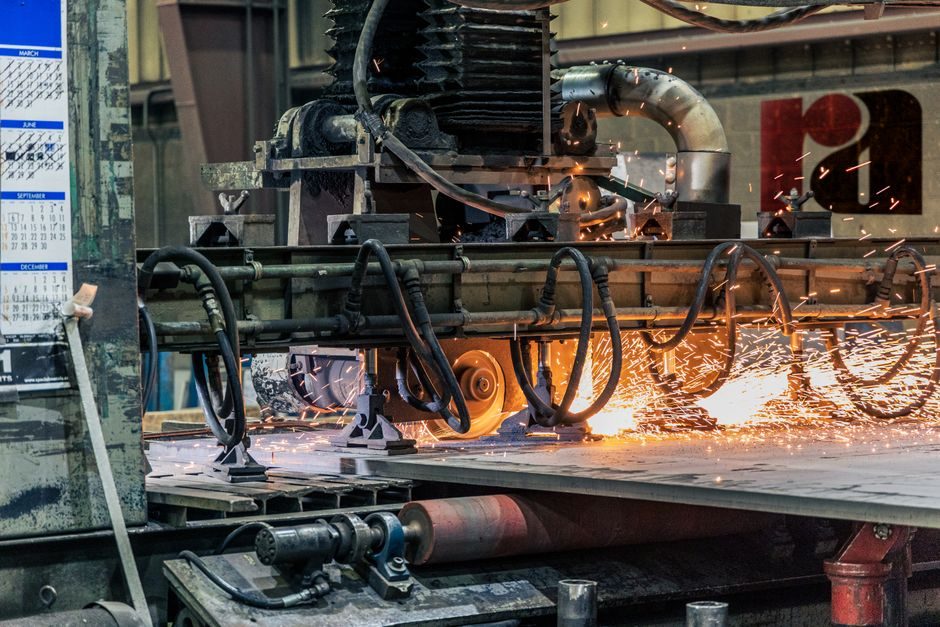
Steel monopile foundations dominate the offshore wind manufacturing order book, with input plates wider than 4.3 m, longer than 15 m, thicker than 15 cm, and weighing up to 40 t each, requiring coastal production sites with parcels up to 100 acres and 8 m deep-draft berths [S1].
Process logic for offshore wind foundations differs from oil and gas: volumes are higher, serial production replaces one-off fabrication, and load-out cadence is continuous rather than project-by-project, with standardization across monopile, jacket, and gravity-base designs now treated as a delivery requirement rather than an option [S2][S6].
Monopile Plate Intake, Rolling and Seam Welding
Monopile manufacture starts with heavy plate receiving, then longitudinal SAW (submerged-arc welding) of rolled cans, with plate thicknesses above 15 cm driving preheat and interpass control beyond standard ship-plate practice [S1]. The rolled, welded cans are then assembled into conical or near-cylindrical sections, with single-piece monopile diameters now reaching 10 m in the largest European serial-production yards [S8].
Monopiles remain the default for shallow (0–15 m) and intermediate (15–30 m) water depths, and the simplicity of a single rolled-and-welded steel tube is the main reason designers have stretched the design envelope so aggressively rather than switching to jacket or gravity-base structures [S10]. This concentration of demand is also what forces the supply chain into a serial, almost automotive-style rolling cadence, with plate-to-pile flow times measured in weeks, not the months typical of oil-and-gas tubular fabrication [S6].
Transition Pieces, Internal Fittings and Grout Connections
Each monopile is paired with a transition piece (TP) that carries the tower flange, boat-landing, J-tube cable guides, and corrosion-protection anodes, with the TP-to-monopile interface grouted or bolted from the same installation jack-up or floating vessel [S5][S8]. Grouted connections are now specified with material certificates, surface-preparation grades (typically Sa 2.5), and shear-key geometry to keep long-term fatigue performance within design limits on North Sea and US Atlantic sites.
For sites with poorer seabed conditions or deeper water, the same substructure category branches into steel tripod, jacket, and concrete gravity-base foundations, with suction-bucket (suction caisson) variants entering the same factory footprint when soil permits suction embedment rather than pile-driving [S5]. Each non-monopile option imposes a different welding, lifting, and outfitting burden, so the manufacturing line layout itself shifts between monopile-dominant yards and jacket-yard configurations.
Jacket and Floating Substructure Fabrication
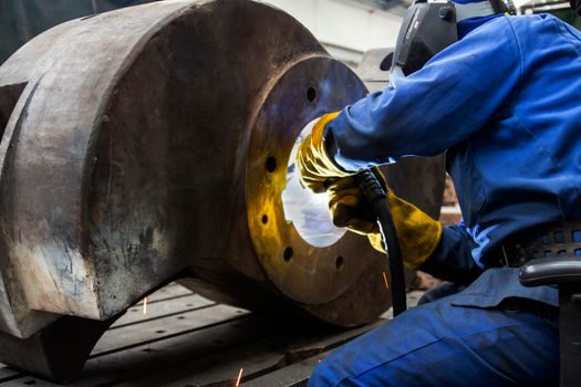
Jacket foundations are built as space-frame tubular assemblies: rolled tubulars are cut to length, end-milled, fitted with conical stubs, and welded into X- and K-joint nodes, then integrated with a TP on top and pin piles or suction buckets at the base [S2]. Jacket-yard throughput is constrained by node-count, weld-deposition rate, and yard crane capacity rather than by plate supply.
Floating wind has introduced a parallel fabrication track — spar buoy, semi-submersible, and tension-leg platform substructures — each of which demands much larger fabrication halls, dry-dock access, or wet-storage quay length, with mooring and anchor systems treated as separate manufactured line items in the 2024 UK Industrial Growth Plan (£10–20 m advanced-material mooring line) [S2][S9]. Foundational comparisons on dimensional envelope, embedment, and scour protection are tabulated in the BOEM 2020-041 white paper, which remains the reference grid for siting decisions in US Atlantic leasing [S2].
Welding Procedure, NDT, and Corrosion Protection
Corrosion protection combines internal coatings, external 3LPE or glass-flake epoxy in the splash zone, and cathodic protection by sacrificial aluminium-indium-zinc anodes mounted on the TP [S5].
Steel plate certification increasingly references EN 10025 for thermomechanically rolled grades, with Charpy impact testing at –20 °C or –40 °C called out for North Sea sites and DNV- or BV-issued mill certificates accompanying every plate lot. The supply-chain roadmap flags plate-mill capacity itself as a bottleneck that has already pushed monopile-dedicated steel contracts above 40 t per plate and into rolling campaigns measured in tens of thousands of tonnes per project [S1].
Load-Out, Marine Logistics and Installation Interface
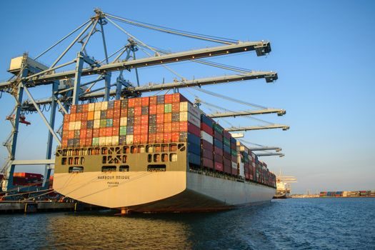
Load-out is engineered around the same 8 m+ deep-draft berth requirement that gates plate intake: monopiles up to 10 m diameter are typically upended on a crawler or hydraulic gantry, lifted onto a transport vessel, and sea-fastened for tow-out to the marshalling port or directly to the installation vessel [S1][S8]. The 2022 Offshore Wind Handbook frames early-stage collaboration between fabricator, installer, and developer as the single largest cost and schedule lever, ahead of welding speed or NDT throughput [S6].
Installation-side decisions still drive the factory: monopiles are installed from jack-up or floating vessels with a transition-piece lift-and-grout (or bolt) step from the same vessel, while two-vessel TP strategies have been used when weather windows compress [S8]. Designers are also pushing toward higher-voltage dynamic inter-array cables (132 kV and above) and the associated TP cable-management hardware, which moves the manufacturing scope deeper into electrical outfitting rather than purely structural fabrication [S9].
Standards, Sourcing and a 2026 Cost Signal
Beyond DNV-ST-0126 (previously used) and the upcoming DNV-ST-0359 family for structural design, manufacturing-side standards include ISO 3834 for welding quality, EN 1090-1/–2 EXC3 or EXC4 for the fabricated steel structure, and ISO 12944 for coating systems — though specific revisions and effective dates should be confirmed against each notified body [S1][S5]. Procurement teams weighing pressure transmitter upgrades for hydraulic pitch and yaw systems alongside flow meter retrofits on grout-plants can be benchmarked against the same fabrication cost line items that are now being audited across US Atlantic monopile contracts.
From a B2B sourcing angle, the relevant component categories that pair with foundation fabrication — industrial valve skids for ballast and grout lines, multifunction process calibrator work for TP sensor loops, and v-process line investments for tower internals — are now bundled into the same UK Industrial Growth Plan envelope (£1.1–2.1 bn for new tower facilities, £0.2–0.3 bn for cable manufacturing) [S9]. For a deeper look at how serial production logic translates to other energy hardware, the manufacturing beat for grid-scale battery storage and the green-hydrogen electrolyzer lines share the same 2026 serial-fabrication playbook.
The next trackable signal is the Q4 2026 US Atlantic monopile awards, where plate-mill allocation and yard throughput — not turbine model — will set the bottleneck; secondary signal is any announced TP-yard capacity above 200 units/year, which would mark a step-change from the 100–150 unit band seen through 2024–2025 [S1][S9].