
Packed plunger pumps rely on a stack of compression-formed packing rings to seal a reciprocating plunger, with documented pressure capability up to and beyond 40,000 psi when configured for high-pressure service [S2]. Packless plunger designs move the dynamic seal off the process fluid by interposing a flexible diaphragm, a bellows, or a sealless magnetic drive between the plunger and the liquid end [S2].
The two architectures split the same reciprocating positive-displacement mechanism, the family covered under plunger pump and broader industrial pump classifications, only at the fluid-end interface, so the choice flows directly from fluid chemistry, pressure class, and leak-tolerance rather than flow rate.
Liquid-End Architecture: Where the Sealing Decision Lives
In a packed plunger liquid end, the plunger extends through a packing stack into a fluid-end chamber, and the seal is made at the packing rather than on the plunger surface itself [S4]. This separation is what allows the plunger to be specified as a hardened, wear-resistant part while the packing is treated as a consumable, a deliberate design split common across reciprocating pumps and hydraulic pump families.
Packing rings in a packed design are typically adjusted at start-up, re-tensioned after a break-in period, and tightened again as the rings wear to hold leakage at an acceptable drip rate [S1]. Williams documentation lists the major sealing components of a packed chemical-injection pump as dual primary and secondary seals, a TFE-composite bearing guiding the plunger, and a bleed valve with a "tell-tale" indicator between the two seal sets so a leak is observable before it becomes a release [S1].
Packed Design: Strengths, Failure Modes, and Maintenance Cost
Packed plunger liquid ends are routinely specified for clean, non-abrasive fluids at moderate to very high pressures, with Chemac (January 2026) explicitly stating that packing designs can handle high pressure up to 40,000 psi or more [S2]. The trade is that the same packing that enables that pressure also leaks by design, with Williams noting that packing "has to be adjusted at start-up and after a break in period" and that "over time as packing wears it requires more adjustment to lessen the leakage" [S1].
Over-tightening the packing to stop a drip is a documented failure path, because the resulting friction accelerates packing and plunger wear, shortens service life, and can score the plunger; the practical alternative is to follow a preventive schedule of repacking rather than chasing leaks with the gland [S1]. For abrasive or solids-laden service, Chemac recommends stepping the liquid end away from packing to a hardened plunger (ceramic or hardened alloy) or, more commonly, to a diaphragm interface, because slurry particles will destroy both packing and plunger surfaces rapidly [S2].
Packless Design: Diaphragm, Bellows, and Sealless Variants
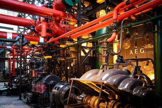
The packless diaphragm liquid end isolates the plunger from the process fluid behind a flexible membrane, so the dynamic seal is made on the hydraulic side, not on the chemical side, which removes the leak path at the plunger altogether [S2]. This is the configuration that dominates chemical-injection skids in oil and gas, where the operator accepts the diaphragm's pressure and temperature limits in exchange for zero process-fluid leakage past the dynamic seal.
Industry-side commentary (Innovative Pumps / Hydra-Cell) frames the difference bluntly: "Packing and seals are the weak point on piston and plunger pumps: they leak, they cause shut downs and they are expensive to maintain" [S8]. Sealless diaphragm (Hydra-Cell-style) designs remove that weak point by replacing both piston seals and packing with a sealed diaphragm cell, at the cost of a more complex flow path and a finite diaphragm life that must be scheduled like a wear part.
Selection Matrix: Fluid, Pressure, Leak Tolerance, Maintenance
Across the four criteria that drive every packed-vs-packless decision, the comparison reads as follows. On fluid cleanliness, packed designs tolerate clean, non-abrasive, low-solids service and fail quickly with slurries; packless diaphragm designs tolerate corrosive, hazardous, and solids-bearing fluids because the diaphragm is the only wetted dynamic part [S2][S8]. On pressure class, packed plunger liquid ends reach the 40,000+ psi ceiling cited for oilfield and waterjet service [S2], while packless diaphragm designs are typically capped well below that ceiling by the fatigue life of the membrane and the permissible differential pressure across it.
On leak tolerance, packed designs are expected to drip and rely on a tell-tale to detect seal failure before product escapes [S1]; packless designs are specified where any process-fluid emission is unacceptable, including offshore, pharmaceutical, and volatile-chemical service. On maintenance, packed pumps need periodic gland adjustment and scheduled repacking plus skilled labour to set the torque correctly [S1], while packless diaphragm pumps trade gland work for diaphragm replacement at a defined stroke-cycle interval. The diaphragm in a diaphragm pump becomes the predictable wear item rather than a packing stack the operator must keep retensioning.
Standards, Sourcing, and Specification Discipline
There is no single industry standard that mandates packed or packless construction for a given service; the choice is driven by API, ASME, and end-user specifications that constrain leak rate, emissions, and material traceability. For high-pressure oilfield pumping, OEM liquid-end designs are patented at the housing-and-packing interface, as in US6623259B1 (Blume, 2003, assigned to Vulcan Industrial Holdings), which details a Y-block transition area and a packing bore geometry where "replacement of plungers and/or plunger packing is significantly more complicated in Y-block designs than in the earlier designs" [S5].
For reciprocating-pump selection more broadly, the engineering reference literature distinguishes plunger and piston configurations and notes that "a plunger pump seal is easier to maintain since it is stationary at the top of the pump cylinder whereas the seal around a piston is repeatedly" stroked, a direct argument for the plunger architecture whenever dynamic-seal life matters [S6]. When the process side will not tolerate a dynamic seal at any pressure, a sealless or diaphragm-topped centrifugal pump alternative may also be evaluated, though at the cost of giving up the pressure ceiling a plunger pump delivers.
Decision Outcomes by Application
For clean chemical injection at moderate pressure (methanol, scale inhibitor, corrosion inhibitor on a wellhead), the packed plunger pump remains the default because of its pressure capability, simplicity, and well-understood gland maintenance [S1]. For the same duty in a Zone 1 hazardous area, where any hydrocarbon emission past the gland is unacceptable, the diaphragm liquid end is the specified substitute, even though it caps the pressure ceiling and adds a diaphragm to the spares list [S2][S8].
For high-pressure waterjet cutting and ultra-high-pressure hydrostatic testing in the 3,000+ bar range, the packed plunger design with ceramic plungers is essentially the only commercial option, because no diaphragm or bellows can survive those pressure cycles economically [S2][S4]. For abrasive mining slurries, drilling fluids with sand content, or any service where particles would destroy packing, the move is to hardened plungers in a packed design only as a last resort; the more reliable path is a diaphragm or sealless interface plus a dedicated flushing plan.
Watch-Items When Specifying Either Architecture
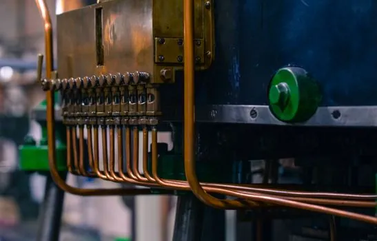
On packed designs, verify the gland hardware allows a real tell-tale between primary and secondary seal sets, confirm packing material compatibility with the specific chemical (TFE, graphite, aramid, and proprietary composites all behave differently with solvents and hot amines), and budget a break-in period in the commissioning plan; packing "has to be adjusted at start-up and after a break in period" before the leak rate stabilizes [S1]. On packless designs, lock down the diaphragm material (PTFE, EPDM, FKM, or alloy-backed), confirm the stated cycle life at the design differential pressure, and require a pressure-relief path on the hydraulic side so a ruptured diaphragm fails safely rather than venting process fluid.
For both, the working pressure envelope matters more than the headline maximum: most field failures of plunger pumps trace back to packing set too tight, a contaminated suction condition causing cavitation, or a material compatibility miss on a wetted elastomer, not to the pump's published pressure rating. The single most useful field practice, applicable to both packed and packless plunger pumps, is a logged leak-rate and stroke-count record so gland or diaphragm replacement happens on a trend, not on a failure.
Track two signals over the next procurement cycle: whether published packing-design pressure ceilings move past the 40,000+ psi benchmark cited in early-2026 trade literature [S2], and whether sealless-diaphragm OEMs publish cycle-life data at the higher differential pressures that oilfield and waterjet users continue to demand.
This topic is covered further in Luffing Jib vs Fixed Jib Crawler Crane: A Spec-Driven Selection.