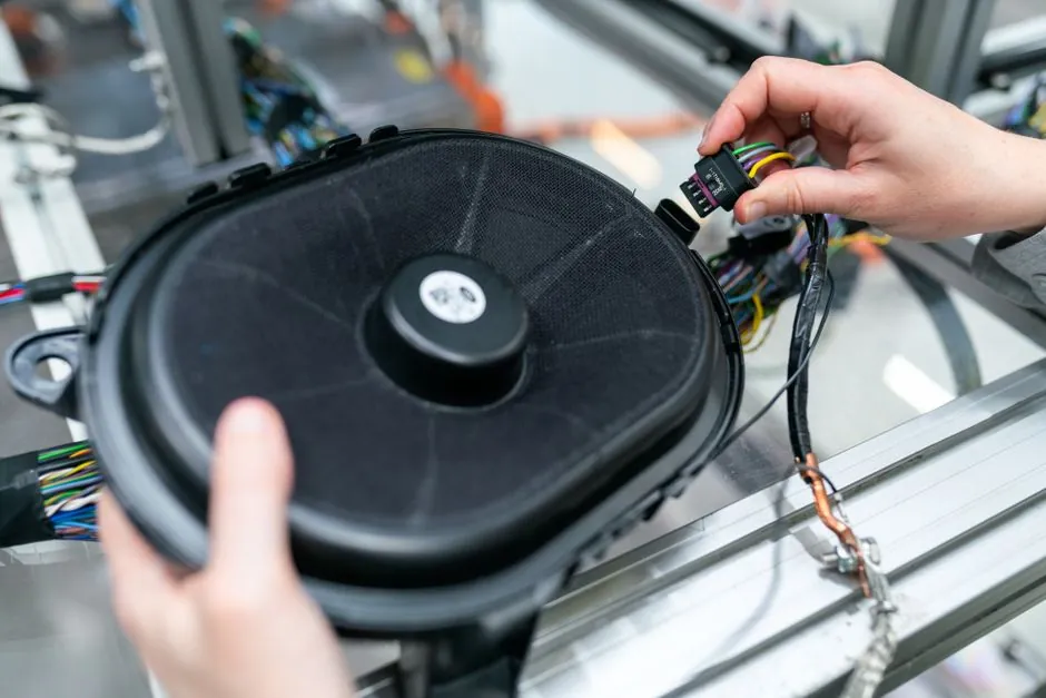
Automated PEM fuel cell stack lines now target 35,000 stacks per year per single production lane, which translates to a ~1 second per cell effective cycle time for an 80 kW light-duty stack of roughly 350 cells, and a roughly 0.5 second per piece handling rate on bipolar plates [S2].
The drivers are cost and yield, not novelty: fewer errors, less floorspace, and less exposure to labor variability. Stack OEMs increasingly want one line that can build both fuel cells and PEM electrolyzers, with leak testing embedded between stacking, banding, and end-of-line conditioning [S2].
Why Leak Testing Lives Inside the Stack Assembly Cell
Fluid leakage in a PEM stack can degrade cell voltage, accelerate membrane degradation, and in hydrogen-rich conditions become a safety hazard, which is why leak test is treated as a process step, not a lab check [S1]. The DOE 2022 manufacturing workshop list for PEM and electrolyzer lines calls out five distinct leak test stations: BPP leak test, BPA leak test, MEA leak test, module leak test, and stack leak test, all positioned upstream of end-of-line functionality and burn-in conditioning [S2].
In practice the cell-level and module-level checks run on a mass-flow basis with air or nitrogen, while helium sniffer or helium-spray methods are reserved for stacks where cross-leak paths between anode and cathode, or to coolant, must be quantified to the sccm level [S3][S4]. The trend is to merge leak test with the pick-and-place robot so that a failed cell or failed plate is rejected without leaving the station, avoiding the cost of stacking a known-bad part.
Stack Sizing Sets the Test Pressure and the Cycle Budget
Notional reference stacks for 2022 cost modeling put a light-duty vehicle stack at 80 kW net, 310 cells, 250-400 cm² active area, 400-600 cm² total plate area, with a 500k system/year volume ceiling. A heavy-duty 275 kW net stack sits at 400 cells, 400-800 cm² active area, and four stacks per system. A 1 MW PEM electrolyzer inverts the ratio: only 150 cells per stack, but ~1,800 cm² active area, and 100 stacks per 100 MW system [S2].
Pressure class follows the application. Stationary and heavy-duty stacks are typically run through a 1,050 bar hydrogen pressure leak test on the pressure-path components, while on the stack-assembly side the integrated leak check sits well below that, in the 1-10 bar range for stack-internal cross-leak characterization, with the helium test reserved for the final acceptance gate [S8]. Helium mass-flow leak testing is favored for cell and module qualification because the gas is inert, the molecular size enables detection of micron-scale path leaks, and recovery is straightforward through a vented test fixture [S3][S10].
Comparing the Main Test Methods on Decision Criteria
Four methods dominate the conversation. Air-under-pressure decay is the cheapest and the fastest at the sub-cell level, but it cannot resolve leak rates below roughly 10⁻³ mbar·L/s and is sensitive to temperature drift. Nitrogen mass-flow testing on assembled cells or modules gives a direct quantitative leak rate, integrates cleanly with robotic handling, and is the workhorse of mid-volume PEM lines [S4]. Helium spray and sniffer testing, including hard-vacuum hood configurations, achieves the lowest detectable leak rates, down to 10⁻⁶ to 10⁻⁹ mbar·L/s depending on chamber design, and is the method of choice for stack-level acceptance and for separator plate sub-assemblies [S3].
Pressure-hold on a sealed module, finally, is a pass/fail step used to screen coolant-circuit integrity before the stack ever sees hydrogen, and it is often run at 1.5-2.0× nominal working pressure with a defined hold time. For high-volume lines, the most common pairing is nitrogen mass-flow at the cell and small-module stages, with helium as the gate before banding and conditioning, which lines up with how dedicated leak-test cell builders structure their stations.
Automation Architecture: Pick-and-Place vs Roll-to-Roll
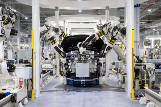
Two automation thrusts coexist in PEM stack manufacturing, and they rarely compete for the same step. Pick-and-place robots dominate the cell stacking, gasket application, and compression/banding steps where discrete parts must be located, oriented, and torqued to a defined compression load. Roll-to-roll or continuous-flow equipment serves the upstream MEA and GDL process steps where parts can be kept un-singulated as long as possible to minimize handling damage [S2].
Fuel Cell ASAP, an ASME-documented program, specifically redesigned stack hardware for robotic assembly, then paired the line with post-assembly leak and burn-in testing so the same fixture that built the stack could also leak-check it without re-clamping [S5]. Commercial integrators have followed the same pattern. Staufermatic integrated an INFICON XL3000flex leak-test module into the Cellcentric heavy-duty fuel cell line, building the leak station into the assembly flow rather than as a downstream island [S6]. Hangke, Marposs, and ATS Industrial Automation offer comparable architectures: pressing, stacking, banding, and leak test share a single backbone, with leak test data written to the same MES record as the torque and compression data [S7][S9][S4].
Test Equipment and What the Spec Sheet Actually Says
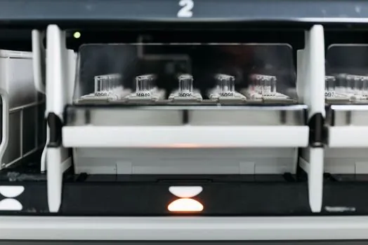
Workhorse leak-test instruments on PEM lines typically combine a pressure-decay channel with a mass-flow channel, share a multi-port manifold, and connect to the line PLC over EtherCAT or PROFINET. Helium leak detectors used at the stack acceptance gate quote a minimum detectable leak in the 5×10⁻¹² mbar·L/s range in vacuum mode and 10⁻⁴ to 10⁻⁶ mbar·L/s in sniffer mode, with a usable test pressure window from roughly 10⁻³ mbar up to 10 bar on the inlet side and a separately rated high-pressure inlet for hydrogen-component testing up to 1,050 bar [S8][S3].
On the assembly side, the pressing machine that sets the cell compression profile before leak test is sized for stack heights from 50 mm (short lab stacks) to 800 mm (heavy-duty multi-hundred-cell stacks), with a pressing force window of roughly 5-200 kN controlled to within ±1-2% via a closed-loop hydraulic or servo-electric actuator [S9]. The clamping force is not optional: under-torque the tie-rods and you get bypass leakage around the gasket, over-torque them and you crack the bipolar plate or crush the GDL, both of which the leak test will flag as a fail.
Limits, Failure Modes, and What Automation Does Not Solve
Even a fully automated stack line will still scrap a fraction of cells, and the leak test is the gate that decides whether a stack progresses to burn-in or is broken back down. Cross-leak between the anode flow field and the coolant manifold is the hardest path to detect on a single-cell fixture, because the leak path runs through the gasket seam and only opens at stack compression. Helium sniffer testing on the assembled stack catches it, but at that point the labor cost of disassembly has already been spent [S1][S3].
For engineering teams evaluating a line, the practical questions are: what is the leak rate threshold per cell and per stack, how is that threshold tied to a standard or to a customer FMEA, and can the test station keep up with the 0.5-1.0 second per piece rate the rest of the cell demands [S2]? If the leak station is the bottleneck, adding robots upstream does not move the throughput number. For integration guidance on how the leak test interlocks with the press and the torque stations, the same controls architecture that pairs a tensile testing machine with a load cell in a materials lab shows up in stack-assembly cells as a load cell module under the press platen.
Standards, Sourcing, and What to Track Next
There is no single IEC or ISO standard that defines a fuel cell stack leak rate, and OEM-specific acceptance limits still vary widely. SAE J2572 and IEC 62282-2 cover fuel cell system safety and performance at the system level, while component-level leak acceptance is typically negotiated between the stack integrator and the OEM customer, then enforced through a documented in-process control plan. For station builders sourcing components, the oxy-fuel cutter and electrical automation encyclopedia pages cover adjacent process steps (frame cutting, fixturing, and PLC integration) that surround the leak-test station on a turnkey line. [S2]
Two signals are worth tracking: published cycle-time data from the DOE 2022 and successor workshops, and the next round of capacity announcements from heavy-duty truck fuel cell programs, where Cellcentric and similar integrators are driving the inline helium test architecture that smaller programs will inherit. A third near-term signal is any tightening of the stack-level leak rate threshold in OEM procurement specs, which is the lever that forces the next automation upgrade from nitrogen mass-flow to helium hard-vacuum at the cell stage.
This topic is covered further in ASTM C578 Type IV vs Type VII XPS: ICC-ES Compliance and Spec Selection.