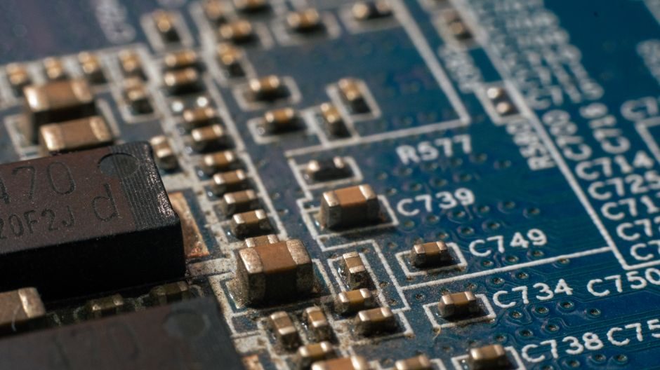
A 100 kW-class PEM automotive fuel cell stack is built from seven functional sub-assemblies — membrane electrode assembly (MEA), gas diffusion layer (GDL), bipolar plates, gaskets, end plates, current collectors and BoP manifolds — with Pt-group catalyst loadings typically held between 0.1–0.4 mg/cm² per electrode in 2024–2026 production programs [S8].
The BoP layer around the stack adds another dozen part numbers: air compressor, hydrogen recirculation blower or ejector, high-pressure Type IV tanks, humidifier module, DC-DC converter and the pressure transmitters, flow meters and load cells used in production-line dosing of catalyst inks and membrane coating [S2][S5].
MEA, GDL and Catalyst Layer: Where 70% of the Stack Cost Sits
The membrane electrode assembly is a five-layer sandwich: PFSA proton-exchange membrane (Nafion-class or short-side-chain equivalent), anode catalyst layer, cathode catalyst layer, anode GDL and cathode GDL, with the membrane typically specified at 8–15 µm for automotive duty and 25–50 µm for stationary units [S8].
Pt/C or Pt-Co/C catalyst is coated onto the GDL or directly cast onto the membrane, with the cathode carrying roughly 0.2–0.4 mg Pt/cm² and the anode closer to 0.05–0.1 mg/cm² in 2024–2026 production data; total Pt content per 100 kW stack is commonly targeted below 10 g, versus >30 g in 2008-era designs [S8].
GDL substrate is a carbon-fiber paper or woven cloth with a PTFE wet-proofing treatment (typically 5–10 wt%) and an optional micro-porous layer (MPL) of carbon black and PTFE (1–3 mg/cm²) on the catalyst-facing side, supplied as roll goods that are die-cut into plates sized to the active area [S5][S8].
Bipolar Plates: Coated Metal, Composite or Graphite
Bipolar plates account for roughly 60–80% of stack weight and 25–35% of stack cost; the three production-grade options are machined or stamped metal (stainless 316L, titanium), compression-molded graphite/composite, and carbon-polymer compound, with the metal route favoured for high-volume automotive lines [S2][S8].
Metal plates require a protective coating to limit passive-layer resistance and Cr-leaching into the MEA — amorphous carbon (a-C), TiNbN, Au, or doped diamond-like carbon are the cited options — with target interfacial contact resistance under 10 mΩ·cm² at 1.4 MPa compaction [S8].
Plate geometry is dictated by the flow-field pattern (serpentine, parallel, interdigitated or bio-inspired), with channel depth typically 0.4–1.0 mm, land width 0.8–1.5 mm and active-area single-plate footprint in the 200–400 cm² range for automotive stacks [S8].
Seals, End Plates and Stack Hardware
Gaskets between every repeat unit are typically cut EPDM, FKM or fluoroelastomer sheet, with thickness 0.15–0.30 mm, and must keep H₂ cross-over below the SAE J2578 / IEC 62282-2 occupational limit of 4 µL/min·cm² at rated differential pressure [S8].
End plates are machined 6061-T6 or 7075-T6 aluminum — sometimes stainless 316L for marine duty — and must hold the cell-to-cell compression uniformity inside ±5% across the active area, usually with load spreading via a Belleville washer stack or a hydraulic bladder [S2][S8].
Tie-rods or band clamps are grade 8.8 / 10.9 zinc-flake or PTFE-coated steel, torqued to a target bolt load that produces 1.0–1.5 MPa average compaction on the MEA, monitored during assembly with load cell modules wired into the press fixture [S2].
Balance of Plant: Manifolds, Sensors and Power Electronics
The BoP layer around the MEA stack includes the air supply (centrifugal or scroll compressor, intercooler, filter), hydrogen supply (regulated 70 MPa Type IV tank, ejector or recirculation pump, purge valve), thermal loop (de-ionized coolant, radiator, oxy-fuel cutter-class stainless manifolds) and a humidification module that maintains inlet RH at 60–100% [S2][S8].
Instrumentation on a production fuel-cell line includes pressure transmitters on the anode and cathode inlet (typically 0–3 bar gauge, HART or IO-Link), Coriolis or thermal-mass flow meters on hydrogen, and conductivity sensors in the coolant loop; these tie into a PLC that sequences stack assembly torque, leak-test and break-in procedures [S2].
Power electronics downstream of the stack are a high-voltage DC-DC boost converter (typically 300–650 V output for automotive drives) and an inverter for traction motors, with ABB and other Tier-1 suppliers publishing robotic assembly cells targeted at fuel-cell stack lines, hydrogen tank lines and battery/power-electronics enclosures at the same plant [S2].
Raw-Material Sourcing Map: Where the Supply Risk Sits

The five supply-risk items in a PEM stack BoM are Pt-group catalyst (South Africa, Russia), carbon-fiber GDL substrate (US, Japan, EU), PFSA membrane (US, Japan), coated-metal bipolar plate (China, EU, Japan) and carbon-composite compression plates (US, EU), and a 2026-sector directory lists AvCarb-style carbon-paper GDL systems with proprietary PTFE treatment and micro-porous layer coating as the lead product class [S5].
Two industry coalitions are tracking the supply chain in 2026: the Ohio Fuel Cell & Hydrogen Coalition, which named Jing Lyon as Executive Director to coordinate education and industry leadership across the Ohio corridor, and the Hydrogen Fuel Cell Bus Council, a coalition of transit agencies, manufacturers and suppliers advancing the FCE-bus economy [S3][S7].
The US Department of Energy continues to anchor outreach and standardisation around Hydrogen and Fuel Cell Day, observed on 8 October (the atomic weight of hydrogen, 1.008) to coordinate national announcements on transportation, stationary power and industrial applications of the technology [S1].
Stack Bill-of-Materials Comparison: Three Routes on Five Criteria
The three bipolar-plate routes line up against the main decision drivers as follows. (1) Metal (coated 316L/Ti): best volumetric power density, lowest plate cost at scale, but coating adds 5–12% to plate price and raises recycling complexity. (2) Expanded graphite: lowest contact resistance, longest lifetime, but brittle in vibration and heavy for automotive packaging. (3) Carbon-polymer composite: lowest weight, easiest to mould into complex flow fields, but bulk conductivity is lower than metal or graphite so plate thickness must grow 1.5–2× to match performance [S8].
For a decision-maker the trade collapses to duty cycle: metal is the default for high-volume light-duty vehicles and Class 8 trucks, expanded graphite remains specified for stationary prime-power units where lifetime dominates, and carbon-polymer is favoured for aerospace and unmanned aerial propulsion where mass is the constraint and peak power density is not [S2][S8].
A 2026 hydrogen sourcing reference compiled by SourceBySpec goes deeper on the raw-material side and pairs a Pt-supply outlook with a coated-metal plate buyer map, summarised in the Hydrogen Fuel Cell Raw Material Sourcing Guide: 2026 Spec Bands, Standards and Supply Map.
Limits, Failure Modes and Open Process Windows

Mechanical failure modes in production are dominated by membrane pinhole formation from over-compression, GDL crushing under non-uniform bolt load, and bipolar-plate coating delamination after thermal cycling; each is caught at end-of-line by a leak-rate test at rated differential pressure and a voltage-uniformity scan across the cell group [S8].
Process-window control is the same problem any high-volume stack maker faces: catalyst ink uniformity, membrane thickness tolerance, GDL PTFE loading and bipolar-plate flatness must all be held inside tight bands before the cell is sealed, which is why a hydrogen fuel-cell line tends to spec the same type of shaft-key press fixtures and torque-controlled assembly cells used in other precision process industries [S2].
A verifiable next node to watch is the Silverchair platform migration planned for summer 2026 by the Royal Society of Chemistry, which will move the journal surface behind which hydrogen-peroxide photo-fuel-cell research is published — a marker that fuel-cell R&D output is being repositioned onto a new indexing surface through 2026 [S9].