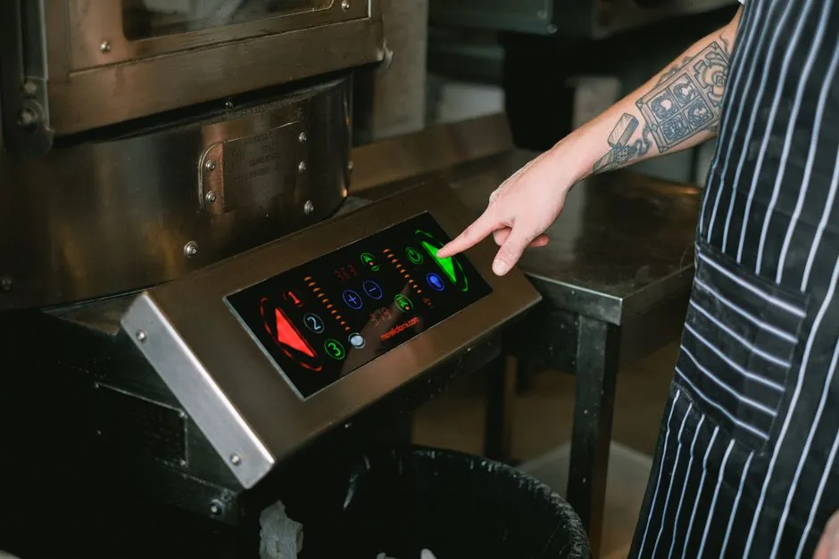
The PID controller is a three-term feedback compensator that drives the error e(t) = setpoint minus process variable toward zero through proportional, integral, and derivative action, with transfer function Kp + Ki/s + Kd·s [S2][S3].
Selecting a controller for an industrial heating or motion loop is a four-axis problem: pick a sensor input family, pick an output stage sized to the load, pick the right term combination (P, PI, PD, or full PID), and pick a tuning recipe. Skip any axis and the loop will oscillate, drift, or fail safe in the wrong direction [S1][S4].
Sensor Input: Thermocouple Types vs PT100 RTD
Most loop problems start at the input terminals, because the controller is only as accurate as the millivolts it sees. Common thermocouple types are K, J, T, E, R, and S, each calibrated for a defined temperature range and atmosphere; type K is the general-purpose workhorse for industrial furnaces, ovens, and plastics processing, while types R and S target high-temperature precious-metal applications [S1].
PT100 RTDs use a 100 Ω platinum element with a positive temperature coefficient near 0.385 Ω/°C and are preferred where long-term stability and repeatability beat the thermocouple's wider span, especially in laboratory, pharmaceutical, and precision industrial systems [S1]. A practical decision matrix: pick a thermocouple when the application exceeds roughly 600 °C, when the probe must respond in under a second, or when budget dominates; pick a PT100 when control accuracy below 1 °C matters more than span, when lead resistance would distort a thermocouple cold-junction, or when the loop runs for years between calibrations.
Output Stage: Mechanical Relay vs SSR Drive
The output stage switches power to the heater, cooler, or actuator and its switching speed sets the floor on loop bandwidth. Relay outputs use mechanical contacts and are cost-effective for slow cycles, but contact wear limits them to applications with long switching periods and modest inrush [S1].
SSR drive outputs deliver a logic-level signal that triggers an external solid-state relay, enabling rapid zero-crossing switching without moving parts, which tightens temperature stability and extends service life in continuous-duty heating [S1]. Decision rule of thumb: a 10 A electromechanical relay is fine when the cycle period is longer than about 30 s, whereas a zero-cross SSR is the right call when cycle periods drop below 10 s, when SCR / heater inrush would weld relay contacts, or when the process cannot tolerate the temperature ripple from a slow cycle.
Control Mode: P, PI, PD, and Full PID
The three terms are not interchangeable: the proportional term Kp reacts to current error magnitude, the integral term Ki accumulates past error to eliminate steady-state offset, and the derivative term Kd anticipates future error from its rate of change, with the full transfer function (Kd·s² + Kp·s + Ki)/s [S2]. P-only control leaves a persistent offset; PI control removes the offset but can overshoot; PD control adds damping but cannot reject a constant load disturbance; full PID is the general-purpose answer when both offset rejection and damping are required [S3][S4].
Set Ki to zero and the PID controller becomes a PD controller; set Kd to zero and it becomes a PI controller; this gain-zeroing trick is the standard way to deploy a single PID hardware block across P, PI, PD, and PID duties [S4]. For a pure temperature loop, a PI with derivative on the process variable (not on the error) is the common industrial configuration that avoids derivative kick on setpoint changes.
Tuning Methods: Ziegler-Nichols vs Model-Based
Ziegler-Nichols remains the baseline recipe: drive the loop with P-only, raise Kp until it sustains oscillation at the ultimate gain Ku with period Tu, then back off the gains to a fraction of Ku and Tu, with classic recommended values of Kp ≈ 0.6·Ku, Ti ≈ 0.5·Tu, and Td ≈ 0.125·Tu for a standard PID [S5]. The catch: Ziegler-Nichols targets a quarter-amplitude-damping response, which is aggressive for processes that cannot tolerate overshoot, such as temperature loops near a product specification limit.
Model-based tuning uses an open-loop step test to identify the process gain K, dead time L, and time constant T, then applies correlations such as Cohen-Coon for lag-dominant processes or Lambda tuning for integrating or noisy loops, often giving a slower but far less oscillatory response [S2][S5]. For a temperature oven, the Lambda rule typically yields Ti ≈ 3·L and Td ≈ 0.5·L, with Kp scaled to hit the desired closed-loop time constant; for a self-regulating flow or pressure loop, Cohen-Coon's faster settings are usually acceptable.
Who Should and Should Not Use Full PID
Full PID is the right pick for second-order or higher systems with measurable dead time, for processes that must hold setpoint within a tight band under varying load, and for multi-loop cascades where the inner loop needs aggressive derivative damping [S2][S4]. It is the wrong pick for very fast processes where the actuator bandwidth is the bottleneck, for highly noisy measurements where derivative action amplifies the noise into output chatter, and for pure first-order self-regulating processes where a PI loop is provably sufficient [S4][S5].
A practical shortlist logic that mirrors how a process engineer would actually buy: first, define the worst-case load disturbance and the acceptable steady-state offset; second, choose a sensor input that exceeds the needed accuracy by at least 3×; third, size the output stage to the heater or actuator current with a 25% derating margin; fourth, default to PI with derivative on PV for most temperature loops, and reach for full PID only when the step response shows clear overshoot after a load change.
Limitations and Failure Modes
Integral windup is the classic PID failure: when the actuator saturates, the integrator keeps accumulating error and the loop overshoots massively when the setpoint finally becomes reachable, so any production-grade PID must include anti-windup, output clamping, or a back-calculation path [S4]. Derivative kick is the second common failure: taking the derivative of the error instead of the process variable spikes the output every time the setpoint steps, which is why most industrial temperature controllers implement derivative on PV [S1][S3].
Lost feedback is the third, and most dangerous, failure mode: if the sensor or wiring opens, a controller without proper failsafe will drive the plant to full power until something burns out, so sensor-break protection, output limits, and independent high-temperature cutouts belong in the loop, not optional in the controller [S4]. Tuning on a model that does not match the operating point is the fourth: a PID tuned at 200 °C will underperform at 400 °C on a non-linear process, which is why gain scheduling or auto-tuning across the expected range is standard on modern instruments [S5].
Spec Shortlist Before You Order

Before specifying a controller, lock these numbers down in writing: sensor input type and standard (IEC 60584 thermocouple letter designation or IEC 60751 for PT100), output stage type and current rating, control mode (P, PI, PD, PID, or PID with derivative on PV), supply voltage, communication protocol if networked, and the intended tuning method with its initial gain target [S1][S2]. For a bench-prototyping reference on closed-loop motion control that complements a temperature loop design, the practical implementation patterns in a PID-driven servomotor test bed using an Arduino-class microcontroller demonstrate how the same three-term math behaves on a completely different plant. The PID controller entry covers the underlying feedback math, while the linear guide and crossed-roller guide references cover the mechanical side of precision motion stages that the PID output ultimately drives.