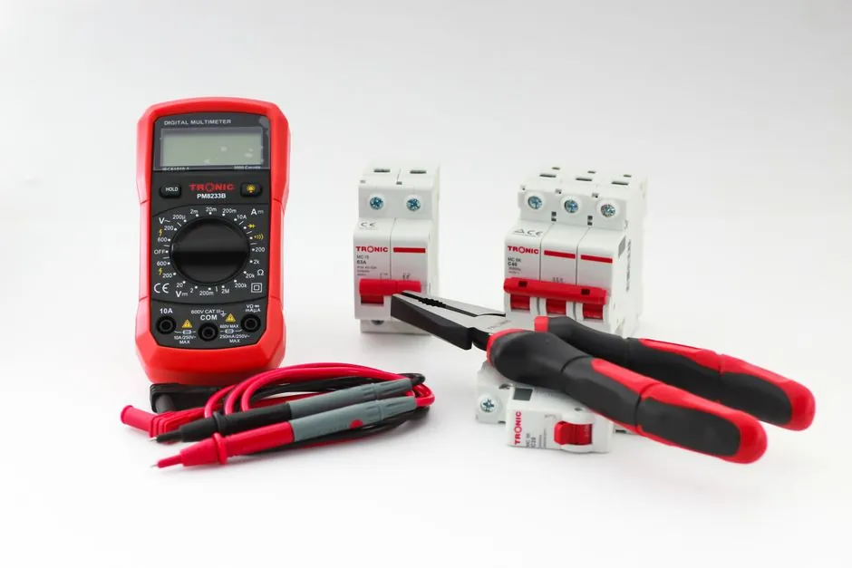
Thermal overload relay selection is a three-axis decision: the relay's adjustable current window must bracket the motor's nameplate full-load amps, the trip class (10, 20, or 30) must match the motor's starting duty, and the mechanical/electrical interface must dock to the contactor or DIN rail without rewiring [S1][S2][S3].
For a 1.1-1.5 A motor on a light-load fan or pump, a relay set to a 1.0-1.6 A range covers the duty; a 15-22 A motor on a compressor line needs a 12-22 A range to land the setpoint inside the middle third of the dial [S2][S3]. Outside that range, nuisance trips on cold starts or silent failures during stall are the two predictable failure modes engineers report in field service logs [S1][S7].
Start at the Motor Nameplate, Not the kW Rating
The motor nameplate's rated current is the single anchor point for thermal overload relay selection; motor power in kW is a secondary cross-check that can mislead because two 11 kW motors from different efficiency classes can draw different full-load amps on the same voltage [S2]. Industry guidance recommends recording rated current (A), rated voltage (V), frequency (Hz), power, and duty type before opening a relay catalog [S1][S2].
After the nameplate data is on the bench, the relay's adjustable range must envelop the motor's rated current with the operating setpoint sitting in the middle of the dial, not at either extreme, so that ambient temperature drift and voltage sag do not push the relay into early trip or late trip territory [S1][S3]. For a 4 A motor, a 2.5-4 A range is a clean fit; a 3-5 A range forces the operator to the lower end and a 4-6 A range blocks adjustment below 4 A entirely [S2][S6].
Trip Class 10 vs 20 vs 30: Match the Starting Duty
Overload relays carry a trip class marking that declares the seconds-to-trip at 6x the full-load current setting: Class 10 trips within 10 seconds, Class 20 within 20 seconds, and Class 30 within 30 seconds, with an unmarked relay assumed to be Class 20 [S4]. Class 10 (typical IEC) suits normal starting of standard induction motors; Class 20 (typical NEMA) gives extra margin for high-inertia loads; Class 30 is the choice for very long acceleration ramps where the inrush must not look like an overload to the heater [S4][S2].
Standard IEC thermal relays are usually adjustable to 50% above the nominal trip current, while NEMA-style relays adjust to about 15% above and below, a mechanical fact that biases IEC designs toward flexible motor swaps on the same frame size [S4]. For motor starting on conveyors, mixers, and crushers where locked-rotor current lasts several seconds, Class 20 is the safer default; for HVAC fans and small pump motors where the rotor is up to speed in under 2 seconds, Class 10 saves cabinet space and reduces nuisance trips [S4][S7].
Heater and Bimetallic Mechanism: How the Relay Actually Trips
A thermal overload relay senses current through a heating element that warms a bimetallic strip made of two bonded metals with different thermal expansion rates; as current rises and the strip bends, the mechanism eventually opens the auxiliary contact wired to the contactor coil, dropping the motor offline [S4][S5]. The same current that powers the motor also powers the heater, so the relay's thermal model is a slow integrator: it ignores short inrush but catches sustained overcurrent that would damage insulation over minutes [S4][S5].
Two trip models are used in modern electronic overloads: the classic I²t curve (energy-accumulating, ideal for standard induction motors) and the two-body model, which simulates stator and rotor heating separately for variable-frequency drives and high-inertia loads [S7]. For a basic across-the-line starter on a fixed-speed motor, I²t is the right default; for VFD-driven motors with extended low-speed running, the two-body model is the better match because it tracks rotor heat independently of stator current [S7].
Contactor Match, DIN Rail, and Short-Circuit Coordination
The relay does not switch the motor; the contactor does. The thermal overload relay sits downstream of the contactor and is wired only into the contactor coil circuit through its normally-closed auxiliary contact, so the relay's frame size and pin layout must physically and electrically mate with the chosen contactor series [S1][S2]. Most IEC manufacturers offer direct-mount and separate-mount variants: direct-mount clips under the contactor for compact panels, while separate-mount (DIN-rail or panel-mount) is used when the relay frame differs from the contactor frame or when space is tight inside the enclosure [S1][S5].
A thermal relay is not a short-circuit protective device. Sustained overload is a thermal fault with seconds-to-minutes timescale; short-circuit current is a magnetic fault that must be cleared in milliseconds by upstream fuses or a molded-case circuit breaker, with the overload relay and the short-circuit device coordinated so the breaker clears faults faster than the relay's thermal element can be damaged [S1][S2]. Skipping this coordination is the single most common cause of welded contactors and burned heater packs in post-incident teardown reports [S1][S2].
Ambient Temperature, Phase Loss, and Reset Behavior
Bimetallic thermal relays are ambient-sensitive: a relay calibrated in a 40 °C panel and installed next to a variable-frequency drive at 55 °C will trip earlier than its nameplate current suggests, so derating or moving the relay to a cooler zone of the cabinet is a routine field fix [S1][S8]. Some relays include phase-loss detection that trips within 3 seconds on a single-phased supply; cheaper units rely on the asymmetry of the bimetal stack to provide the same effect, but with longer trip times and less repeatable behavior [S1][S3].
Reset mode also matters for uptime. Manual reset forces an operator to press a button after a trip, which prevents auto-restart into a still-faulted condition; auto reset re-closes the auxiliary contact after a cooldown delay, which suits unattended pumping or HVAC skids but is unsafe on conveyors and machine tools where the motor must not restart under a person's hand [S1][S2]. For most industrial OEM panels, manual reset is the default; auto reset is reserved for remote, inaccessible installations where a service call costs more than a guarded restart [S1][S2].
Side-by-Side Comparison of Common Options
Four practical options cover most low-voltage motor starter builds, and they line up against four decision criteria: adjustable range width, trip class, mounting style, and reset flexibility. The table below is the field-engineer shortcut for picking the right family before opening a datasheet [S1][S2][S3][S4].
Option A: Direct-mount bimetallic, Class 10, 1.0-1.6 A to 9-13 A ranges, manual/auto reset, contactor-mounted. Best for OEM pump and fan panels under 15 kW where cabinet space is tight and the relay never needs to be replaced independently of the contactor [S1][S2].
Option B: Separate-mount bimetallic, Class 20, 12-22 A to 80-100 A ranges, manual reset, DIN-rail. Best for retrofit jobs on existing NEMA contactors where the relay must live away from the contactor body and the motor draws heavy starting current [S1][S3][S4].
Option C: Electronic (solid-state) overload, selectable Class 10/20/30, 0.1-1.0 A up to 100-630 A ranges, manual/auto reset, separate-mount. Best for premium motor panels with VFDs, two-body thermal model, and remote trip signaling over IO-Link or Modbus [S5][S7].
Option D: Thermal relay with phase-loss detection and ambient compensation, Class 10 or 20, mid-range currents, manual reset, contactor-mounted. Best for three-phase installations in outdoor cabinets, agricultural pumps, and chemical skids where a single-phase event is a realistic fault mode [S1][S3][S8].
Who Should NOT Pick the Cheapest Bimetallic Relay

The lowest-cost direct-mount bimetallic relay is the wrong choice on VFD-driven motors, because the relay's heater only sees the fundamental output current and ignores the additional I²R heating from the drive's PWM ripple; for those duties, an electronic overload with a two-body thermal model is the spec-compliant answer [S7]. It is also the wrong choice for high-cyclic-load applications (more than 60 starts per hour) where the bimetallic element does not have time to cool between cycles and walks toward an early trip [S4][S7].
For hazardous-area installations, a standard thermal relay on its own does not provide the explosion protection required; the relay and contactor combination must be specified as a unit for the area classification, with the relay's enclosure and terminal blocks meeting the same ingress and gas-group requirements as the rest of the starter [S1]. The relay's trip accuracy will also drift by roughly 1-2% of full-scale per 10 °C of ambient swing, so for precision process lines (textile winders, film extruders) a closed-loop electronic overload with a remote current transformer is the spec-correct path [S5][S7].
Quick Shortlist Logic for a Buyer
If the motor is fixed-speed, the contactor is already chosen, and the panel is indoors at < 40 °C, start with a direct-mount bimetallic relay in Class 10, dialed to the motor nameplate amps, with manual reset [S1][S2]. If the motor is high-inertia or starts under load, step to Class 20 or Class 30 within the same product family rather than swapping to a different vendor [S4]. If the motor is VFD-driven, skip the bimetallic family entirely and select an electronic overload with selectable class and two-body thermal model [S7].
For more context on how a thermal relay fits into a complete motor-protection package, including enclosure and coating choices for harsh process environments, see the motor protection spec map for chemical processing guide. For applications where the contactor is paired with a braking resistor across the drive's DC bus, the brake resistor sizing and selection reference covers the matching duty cycle. A basic thermal relay primer is also available in the encyclopedia section, and broader contactor and industrial relay selection logic is covered separately for non-overload switching duties.
The underlying component specifications are covered under thermal imager.