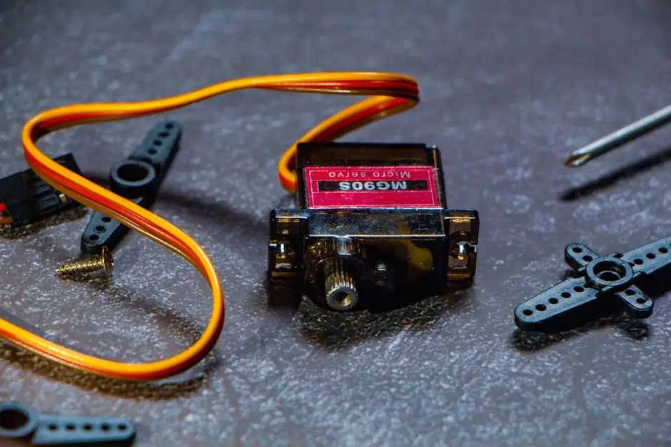
Piezoelectric and electromagnetic screw-driven electric linear actuators both target nanometre-class positioning, but they differ by roughly two orders of magnitude in stroke, force, and how they hold position when unpowered [S1][S4].
The decision matters in semiconductor metrology, photonics alignment, and AFM-class instrumentation, where the wrong actuator class adds backlash, drift, or thermal load to a closed-loop optical path [S4][S6].
Operating Principle and Resolution Class
Piezoelectric actuators exploit the inverse piezoelectric effect, where an applied voltage on a piezoceramic stack induces strain that physically elongates or shortens the element, and a piezo motor then couples that strain to a moving carriage through a flexure, inertia, or ultrasonic drive train [S4][S6]. In contrast, electromagnetic screw-driven actuators combine a rotary stepper or servo motor with a lead screw or ball screw, converting rotary motion into linear displacement through a nut that travels along the screw thread [S1][S2].
Quantitative resolution separates the two classes: PI's servo/stepper actuator families specify 0.05 µm minimum incremental motion with 4 nm encoder resolution, 0.1 µm MIM with 7 nm sensor resolution, and 10-25 mm travel across the captive product line [S1]. Piezo stepper and inertia stages reach single-nanometre minimum incremental motion with strokes to a few hundred micrometres, while ultrasonic piezo stages trade to a few hundred nanometres MIM over up to 50 mm stroke [S4].
Stroke, Force, and Speed Trade Space
Stroke is the dominant divider: piezo stages cap at roughly 0.5 mm in compact packages and about 50 mm for ultrasonic variants, whereas electromagnetic screw-driven units deliver 10-50 mm in the PI C-663 family and continue to rodless linear motor stages for longer travel [S1][S4].
Force runs in the opposite direction: lead-screw actuators hold 40-70 N push/pull in the captive PI range, ball-screw recirculating designs trade some holding force for higher velocity, and piezo stepper stages sit near 10 N while ultrasonic piezo stages top out at a few newtons [S1][S4]. Speed similarly inverts the comparison, with screw-driven units in the 0.75-1.5 mm/s range for captive compact models, ultrasonic piezo stages near 200 mm/s, and piezo stepper stages around 10 mm/s [S1][S4].
The table below lines up the option classes against four decision criteria typical of a spec sheet.
Criterion: minimum incremental motion. Piezo stepper and piezo inertia stages reach the single-nanometre range, ultrasonic piezo stages sit at a few hundred nanometres, and screw-driven lead-screw or ball-screw units are specified at 0.05-0.1 µm (50-100 nm) [S1][S4]. Criterion: maximum stroke. Screw-driven captive units cover 10-50 mm, ultrasonic piezo stages cover up to 50 mm, and direct piezo stacks cover hundreds of micrometres [S1][S4]. Criterion: continuous holding force when powered off. Lead-screw actuators are self-locking at 40-70 N, ball-screw units drop because recirculating rolling friction reduces passive holding, and piezo stages hold their position purely by stiction and ceramic stiffness, so holding force is high relative to size but the joint is rigid, not compliant [S1][S4]. Criterion: typical max velocity. Ultrasonic piezo stages lead at roughly 200 mm/s, piezo stepper stages at about 10 mm/s, and screw-driven captive units at 0.75-1.5 mm/s, with rodless linear motor stages extending much further for long-stroke applications [S1][S4].
Closed-Loop Behaviour, Drift, and Heat
Closed-loop position is normally closed with a linear encoder mounted to the moving carriage; PI specifies 4 nm and 7 nm sensor resolution for its captive servo/stepper actuators, while ball screws used with a suitable linear encoder can in well-controlled environments reach the nanometre level, but pulsations from balls entering and exiting the load zone reduce smoothness compared with piezo direct drives [S1][S4].
Heat behaves differently in each class. Recirculating ball-screw actuators generate less heat than sliding lead screws at high duty cycle and high velocity, but reduced friction also reduces holding force when de-energised, and that friction is a continuous thermal load into the optical bench [S1]. Piezo stages draw current only during motion, so they produce no steady-state heat while holding a setpoint, which is a primary reason piezo-driven stages are favoured in microscopy and other optical applications where thermal drift would otherwise dominate [S4].
For applications that need controlled contact force, an electric actuator with a force sensor, such as a voice coil stage, can complement a piezo positioner; this is a common pattern in switch testing and touch-surface characterisation [S1].
Selection Criteria by Application
For sub-100 µm closed-loop optomechanical stages, microscopy focus drives, and laser-cavity mirror mounts, piezo stepper or piezo inertia stages are the first choice, with MIM in the single-nanometre range, passive holding at power-off, and zero heat into the optical path [S1][S4][S6].
For 10-50 mm travel under load, such as fibre-alignment translators that need to bridge a coarse 25 mm sweep and a fine piezo trim, screw-driven lead-screw or ball-screw actuators with 4-7 nm encoder feedback fit, accepting the 50-100 nm MIM limit in exchange for 40-70 N push/pull force and self-locking at power-off [S1].
For long-stroke positioning in the hundreds of millimetres, rodless linear motor stages become the appropriate electric linear actuator class, since neither piezo nor captive screw units reach that travel, and the screw-versus-piezo comparison is no longer the controlling decision [S1].
Limitations, Failure Modes, and Integration Cost
Piezo actuators are not suitable where long mechanical stroke, high continuous force, or low unit cost is the dominant requirement; their short stroke, lower force envelope, and need for a high-voltage drive push up system cost and integration complexity [S3][S4][S5].
Screw-driven actuators are not suitable where motion smoothness at the nanometre scale is the top requirement, because ball-screw pulsation and lead-screw sliding friction both inject periodic error into a position trace that a piezo direct drive does not produce [S4]. Lead-screw actuators also have limited service life compared with recirculating ball screws at high duty cycle, and they trade that longevity for self-locking holding force [S1].
For comparison-class articles on adjacent motion components, see the spec-level guide on contact vs non-contact displacement sensors, which pairs naturally with closed-loop position feedback on either actuator class, and the bearing selection context that determines how a screw-driven stage carries its load [S1].
Standards, Sourcing, and Spec Discipline
No single IEC or ISO standard governs the resolution and stroke figures cited above, so spec comparisons should be drawn from manufacturer datasheets with a defined test condition (sensor resolution, MIM under closed loop, force at a stated duty cycle) rather than from a generic standard number [S1][S4]. The relevant performance data is concentrated in OEM datasheet tables such as the PI captive actuator family, where travel, MIM, sensor resolution, max velocity, and push/pull force are reported per model in a single block [S1].
For a 2026-09-30 spec review, the practical filter is: piezo stepper or piezo inertia stages for single-nanometre MIM over a few hundred micrometres, ultrasonic piezo stages for hundreds-of-nanometres MIM over up to 50 mm, and electromagnetic lead-screw or ball-screw actuators for 10-50 mm travel at 40-70 N force with 0.05-0.1 µm MIM [S1][S4].
Trackable next signals for a process engineer include new piezo stage releases extending stroke past 50 mm with single-nanometre MIM, and screw-driven actuator families reporting closed-loop sensor resolution below 4 nm at the 10 mm travel class, both of which would shift the trade space described above [S1][S4].