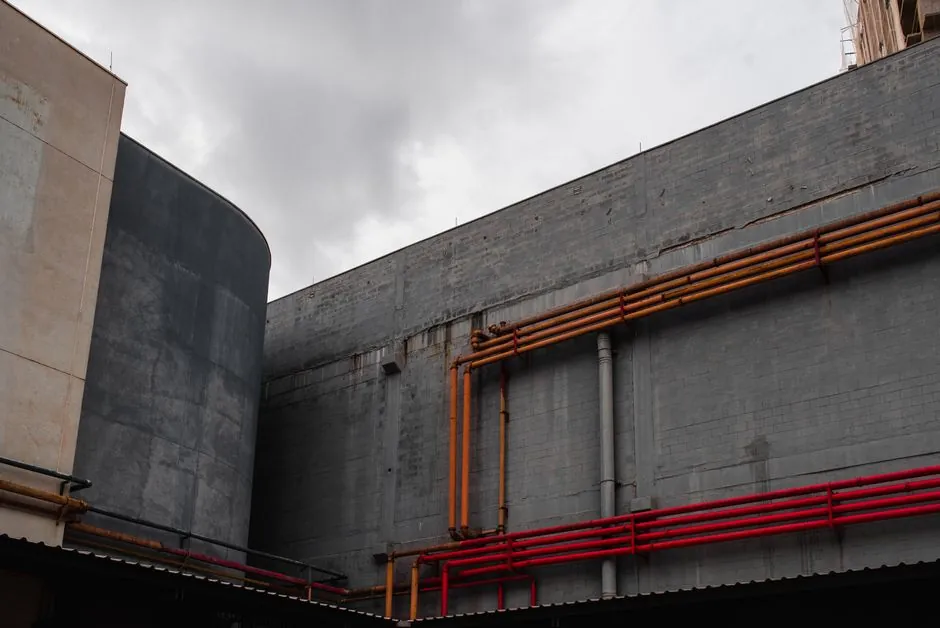
Line routing dictates reliability in pneumatic conveying: every elbow adds pressure drop and accelerates bend wear, so the shortest path with the fewest bends, sized at 4D to 6D radius, is the default design rule on new bulk-solids lines [S9].
Pneumatic conveying moves dry bulk material through an enclosed pipeline using positive pressure or vacuum, with dilute-phase systems typically operating at 4,000 to 8,000 fpm gas velocity and dense-phase systems running below the material's saltation velocity [S2]. Bend geometry and vertical-lift sequencing are the two layout variables that most often determine whether a line runs clean or plugs within weeks of start-up.
Why True Vertical and True Horizontal Beats Inclined Runs
True vertical and true horizontal routing is the preferred geometry whenever structural constraints allow it, because inclined pipe sits between the two stable flow regimes and is the most common source of saltation, dune formation, and uneven wear [S1]. Inclined sections between horizontal and vertical should be avoided where possible; if a sloped run is unavoidable, it is treated as a separate design case rather than a relaxed horizontal [S6].
The pipeline may include vertically up and vertically down sections to cross roads, railways, or to clear obstructions, and these vertical changes are not intrinsically limited in number provided the conveying velocity stays above saltation at the top of each lift [S3]. Designers therefore route the line as a sequence of pure-vertical and pure-horizontal legs joined by elbows, instead of a continuous diagonal.
Bend Radius Selection: The 4D to 6D Working Range
Long-radius elbows sized at four to six pipe diameters are the standard compromise for dilute-phase pellet and granular conveying, balancing pressure drop, product attrition, and the floor space available for the routing [S9]. Sharp short-radius elbows (R/D in the 1 to 2.5 range) generate high pressure drop, accelerated wall erosion on abrasive materials, and measurable breakage on fragile products [S5].
Long-radius bends in the 8D to 14D range are usually the best compromise on space, product impact, durability, and pressure drop, and are the only radius class recommended for dense-phase conveying because shorter bends add unacceptable pressure loss [S5]. Very long radius bends in the 15D to 24D range can backfire: the material bounces repeatedly inside the long arc, which re-introduces attrition and may produce internal build-up rather than eliminating it [S5].
Curvature is defined as the radius of the circle fitting the bend divided by pipe diameter, so a 3D bend has a curvature radius equal to three pipe diameters; under 1.5D behaves like a standard 90 degree elbow, while a 5D bend reads as a smooth bow between two straight pipe sections [S4].
Pick-Up Point Rule: 4.5 m to 6 m of Straight Pipe Before the First Bend
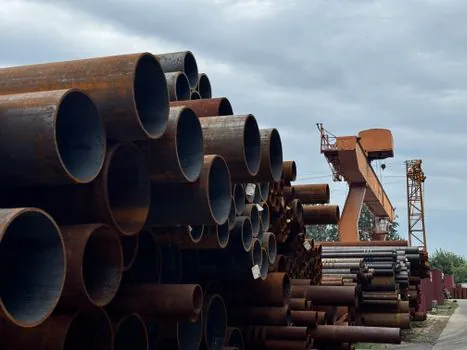
The first bend must never sit immediately after the pick-up point, because the air/solid mixture is not yet stabilised in velocity or distribution; the standard rule is to keep at least 4.5 m of straight pipe, rising to 6 m when long-radius bends are used, so the flow can develop before the first direction change [S5].
Back-to-back elbows should be avoided because they compound pressure drop, double the wear zone, and remove any chance for re-acceleration between direction changes [S6]. The pipe sizing and slope must match the solids characteristics and intended conveying rate, otherwise a layout that looks correct on paper will plug or wear through within a shift envelope [S8].
Bend Effects: Pressure Drop, Wear, and Plugging
Each bend imposes a pressure drop because the solids decelerate on impact with the outer wall and the system must re-accelerate the material downstream, which is why pressure-drop profile is steepest just after the elbow, not at the elbow itself [S5]. The pressure drop also raises pellet speed, so a high-loss bend can shift the line from a stable velocity into an erosion regime within a few operating cycles [S4].
If pressure drop at a bend is too high, the product can settle and block the line, especially in dense-phase operation where saltation margin is small; this is the dominant failure mode on under-sized bends [S5]. Common diagnostic findings on new lines where bend routing was treated as an afterthought include choking, capacity loss from excess pressure drop, conveyed-product damage, and internal build-up [S5]. For broader context on how conveying pipelines fit into plant material handling, see the conveying equipment reference.
Vertical Lifts: Routing Up, Routing Down, and the Saltation Ceiling
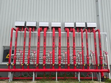
Pipelines can run horizontally and, with bends, transition vertically up or vertically down with little restriction on the number of bends as long as conveying velocity is held above saltation through every vertical section [S7]. Vertical-up runs are the most demanding on blower pressure because the air/solid mixture has to be lifted against gravity in addition to friction loss.
Vacuum systems are useful when material is collected from multiple pickup points and benefit from inward leakage, which helps with dust control at transition points such as elbows, vertical lift modules, and receivers [S2]. Positive-pressure systems are more common on long single-source lines where the vertical lift is significant and a stable push at the pick-up is preferred [S2].
Comparison: Bend Radius Options Against Decision Criteria
The four practical bend classes can be lined up against the criteria that drive most purchase decisions. The "Very Short" class (R/D 1 to 2.5) offers minimum footprint but ranks worst on pressure drop, wear, and product damage, and is only acceptable where space is hard-constrained [S5]. The "Short" class (R/D 3 to 7) is broadly usable but still scores poorly on pressure drop and is restricted to space-bound layouts [S5].
The "Long" class (R/D 8 to 14) is the best general-purpose choice and is the only category recommended for dense-phase conveying [S5]. The "Very Long" class (R/D 15 to 24) reduces impact at the entry of the bend but introduces multiple internal bounces and possible build-up, so it is situational rather than a default upgrade path [S5]. Proprietary designs (often built on short or very short geometry with an internal material pocket) cut attrition in chemical service but are less attractive in food or pharma where pocket renewal cannot be guaranteed [S5].
Use Cases, Limits, and What to Watch on Site
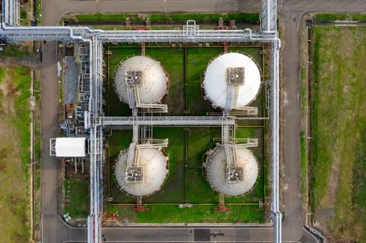
Pneumatic conveying is used across cement, fly ash, food processing, chemical, minerals, and plastics because enclosed piping limits dust and has relatively few moving components, but each of those industries imposes different constraints on bend material and radius selection [S2]. Dense-phase operation is preferred for abrasive or fragile materials at lower velocity, although not every bulk solid behaves well in dense phase and lab testing is normally required before committing to a commercial layout [S2].
The pressure drop through an inclined pipe is generally higher than through a horizontal pipe at the same mass flow, which is why inclined-only routing is a common source of capacity shortfall and is rejected as a substitute for a true horizontal-plus-vertical layout [S2]. On existing systems, capacity upgrades are often limited less by the blower and more by the bend count and minimum radius already in the line, which is why re-routing typically beats re-sourcing the compressor. For a related bulk-materials routing comparison, see pipe conveyor vs troughed belt conveyor on curved routes.
Standards, Sourcing, and Engineering References
The Handbook of Pneumatic Conveying Engineering treats horizontal-plus-vertical routing with bends as the baseline case and notes that the number of bends is not intrinsically restricted provided conveying velocity stays above saltation at every point [S7]. Vendor and engineering sources broadly agree on the 4D to 6D long-radius default for dilute-phase pellet and granular service, and on the 4.5 m to 6 m straight-pipe rule after the pick-up point [S5][S9].
Dilute-phase design runs typically at 4,000 to 8,000 fpm gas velocity, with the correct value set by the saltation velocity of the specific material, and dense-phase design runs below saltation in plug, slug, or dune flow patterns depending on the product [S2]. Where pipework is part of a dust-controlled process, lamps and light fittings and lighting equipment used in the same envelope must be selected for the zone classification set by the conveying system, not the other way around.
Track these signals on the next design pass: the number of bends in the as-built routing versus the 4D to 6D radius rule, the straight-pipe length after the pick-up point against the 4.5 m to 6 m minimum, and the saltation velocity margin at the top of the highest vertical lift, since those three numbers account for most field failures on new pneumatic conveying lines [S5][S7][S9].