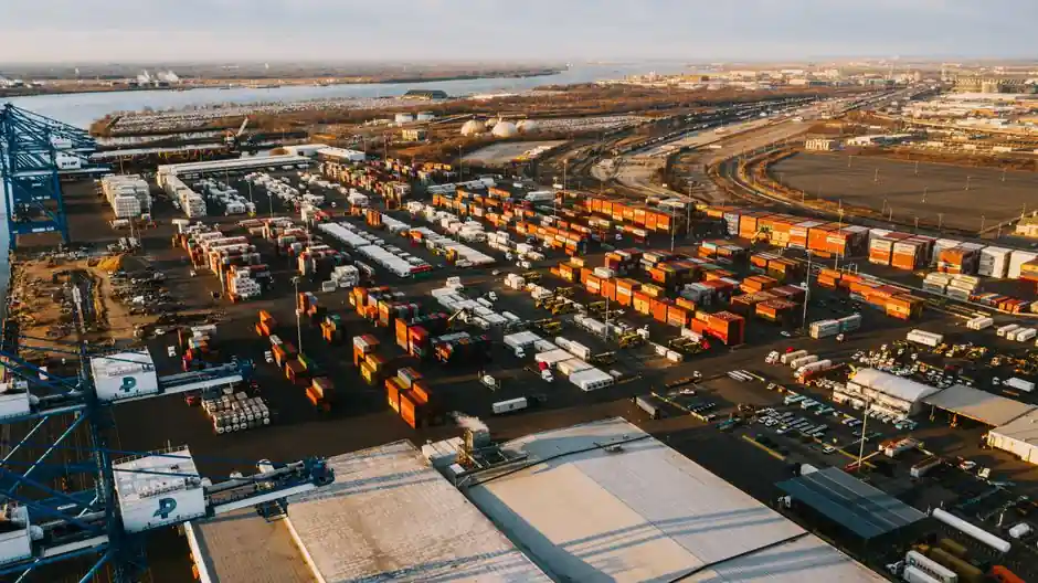
Port terminals handling cement, fly ash, alumina, grain and plastic pellets rely on pneumatic conveying to move dry bulk from ship unloaders and barge hoppers to silos across 50-400 m horizontal runs, with dilute-phase and dense-phase designs split by solids-to-air ratio and conveying velocity [S1][S2].
Dilute-phase systems typically operate at 1,500-7,000 ft/min (roughly 8-36 m/s) with low solids loading, while dense-phase systems run at lower velocities and high solids-to-air ratios to cut particle degradation, elbow wear and dust generation at the berth [S1][S3].
Dilute-phase vs dense-phase: when each fits a port
Dilute-phase conveying is the workhorse for free-flowing, non-friable bulk at port terminals, because high air velocity carries cement, fly ash and pellet material in suspension through simple pipelines and bends with predictable pressure drop [S1]. Dense-phase conveying, by contrast, moves material as plugs or slugs at lower velocity and is preferred for fragile pellets, abrasive minerals, or hygroscopic powders where attrition, line wear and moisture pickup would otherwise drive losses [S1][S3].
Selection at a port should be driven first by material physics, not by the existing blower inventory: bulk density, particle size distribution, moisture behavior, friability and abrasion hardness dictate the flow regime before pipe size, air mover or filter receiver are chosen [S3]. A cement or fly-ash unloader feeding a 10,000 t silo typically pairs well with dilute-phase positive-pressure; a plastic-pellet ship-to-silo line with multiple 90 deg elbows is a dense-phase candidate [S1][S3].
Pressure, vacuum and combined modes for ship-to-silo transfer
Pneumatic systems for port logistics are built in three architectures: positive pressure, vacuum, and a combined pressure-vacuum (push-pull) arrangement, each matched to the layout of unloaders, hoppers and silos [S1][S5]. Positive-pressure systems use a blower or compressor upstream of the feeder and are favored for long horizontal runs from quay to silo farms; vacuum systems pull material from multiple pickup points into a central receiver and suit ship unloader duty with several barge or grab hoppers [S1][S5].
Vacuum conveying is generally capped at shorter distances and lower capacities than positive pressure, but it eliminates dust leaks at the pickup and simplifies ATEX zoning around the unloader, where fugitive dust and ignition risk concentrate [S1][S5]. Push-pull systems combine a vacuum pickup at the ship side with a positive-pressure line to the silo, and are common in cement terminals where the unloader moves between berths while the silo layout is fixed [S1].
Component map: blowers, rotary valves, receivers and filters
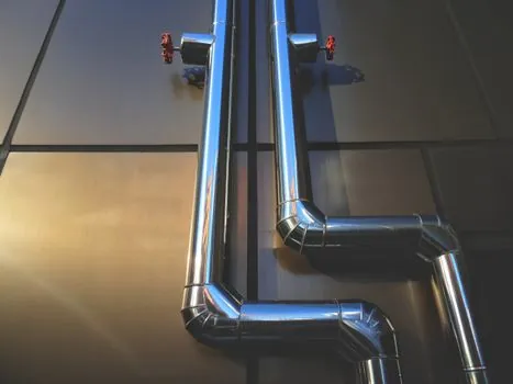
Core components of a port pneumatic line include the air mover (blower, compressor or vacuum pump), rotary airlock or blow-tank feeder, conveying line, filter-receiver, diverter valves and instrumentation for pressure, flow and temperature [S1][S3]. Rotary airlock valves isolate the pressure/vacuum sections and meter material into the line, while filter-receivers separate product from air at the silo top to keep dust below regulatory thresholds [S1].
For port cement and fly ash service, common hardware patterns include positive-displacement blowers rated for 0.5-1.0 bar gauge, dense-phase blow tanks for plug formation, and bag-filter receivers sized for the terminal's peak unload rate [S1]. Instrumentation choices should track conveying-line pressure, air flow, and bearing temperature, because silent drift in any of these is what drives elbow erosion and unexpected downtime at the berth [S3].
Wear, dust and ATEX: port-side failure modes
The two recurring failure modes at port pneumatic installations are elbow wear from abrasive cement or mineral dust, and dust emissions at pickup points that drive both environmental non-compliance and ignition risk [S1][S3].
In European ports, terminals handling combustible dusts such as grain, sugar, alumina or certain polymer powders must size the conveying line and dust-collection system to meet ATEX 2014/34/EU equipment zoning and IEC 60079-series electrical requirements in classified areas, which usually drives the move from dilute-phase to enclosed dense-phase operation at the unloader [S1][S3]. Dust-controlled, enclosed conveying is also a primary reason port operators select pneumatic over open mechanical conveyors like belt or screw units at the ship-to-silo interface [S2].
Comparison: dilute-phase, dense-phase and mechanical at the berth
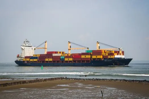
Across the three practical options for a port unloader, dilute-phase pneumatic scores high on simple routing and lower capital cost, dense-phase pneumatic leads on dust control, low velocity and gentle handling of fragile pellets, and mechanical conveyors (belt, screw, drag-chain) lead on visible, high-capacity transport for short, straight runs where dust is not a regulatory driver [S2]. Mechanical systems carry higher material-handling capacity per unit width and tolerate variable particle sizes well, but they expose product to ambient air, limit routing around dock obstacles, and create housekeeping loads at the berth [S2].
For a single decision matrix: pick dense-phase pneumatic when the material is friable, abrasive or combustible-dust classified, the run exceeds 100 m, or multiple bends are unavoidable; pick dilute-phase pneumatic when the material is free-flowing and non-friable, the run is under 300 m, and the terminal already operates a positive-pressure blower room; pick mechanical conveying only when the run is short, straight, the material tolerates open handling, and the terminal's dust zoning is not the binding constraint [S1][S2][S3].
Capacity, air demand and energy at the silo
System capacity at a port terminal is set by the conveying-line diameter, solids loading ratio, and air mover size, and the energy cost is dominated by the air mover, not the pipe [S1][S5]. Dilute-phase lines for cement at 50-100 t/h typically operate at 15-30 m/s with solids-to-air ratios below 10:1, while dense-phase blow tanks for the same material move plug flow at 1-8 m/s and much higher ratios to limit air demand [S1][S3].
Compressor and blower room sizing should follow the terminal's peak ship-unloader rate, not the average, because port pneumatic systems are sized for short, intense unload windows and then sit idle: a 500-1,000 t/h cement unloader with multiple destinations usually needs a dedicated positive-displacement blower and a backup unit, with receiver volume sized to absorb line surges at the diverter [S1][S5].
Selection workflow for a port engineering team
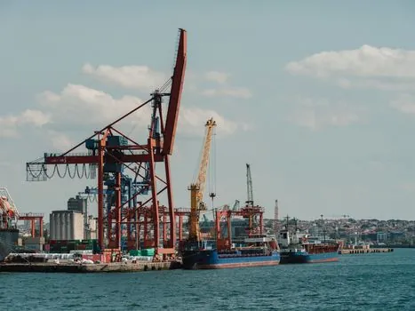
A repeatable port-side selection flow starts with material profiling (bulk density, particle size, moisture, friability, abrasiveness, explosibility), then maps the route (length, bends, vertical lift, number of pickup and discharge points), then picks the flow regime (dilute, semi-dense, dense), then the mode (pressure, vacuum, push-pull), and only then sizes the air mover, pipe and filter-receiver [S1][S3][S8]. Equipment builders such as RIECO, Atlas Copco, Nol-Tec Systems and Fuller Technologies publish reference duty points for cement, fly ash, alumina, grain and plastic pellets that engineers can use as a sanity check before tender [S4][S5][S8][S9].
Final sizing should include a saltation-velocity margin (typically 1.25-1.5x pickup velocity for the design particle) to keep the line away from instability, plus a pressure-drop budget that accounts for every elbow, tee and diverter, since a port line that "almost" meets rated pressure drop is the one that plugs during a storm when the ship is still alongside [S3][S8]. For deeper selection on chemical berths, see this Pneumatic Conveying Selection for Food and Beverage: A Spec-Anchored Map, and for cross-checks against dust-classified solids see Selecting Pneumatic Conveying for Chemical Shipping: A Spec Map. Reference material on pneumatic conveying and the underlying pneumatic conveying system technology base is also available.
Trackable signals for a port tender over the next quarter: confirmed ATEX/IECEx zoning of the unloader enclosure, the duty point (t/h, distance, bends) on the data sheet, and whether the supplier has published a reference list for cement or grain terminals of comparable size, since port duty exposes any over-rated air mover or under-rated filter within the first shipload [S1][S3][S8].
For the relevant spec sheets and selection criteria, see conveying.