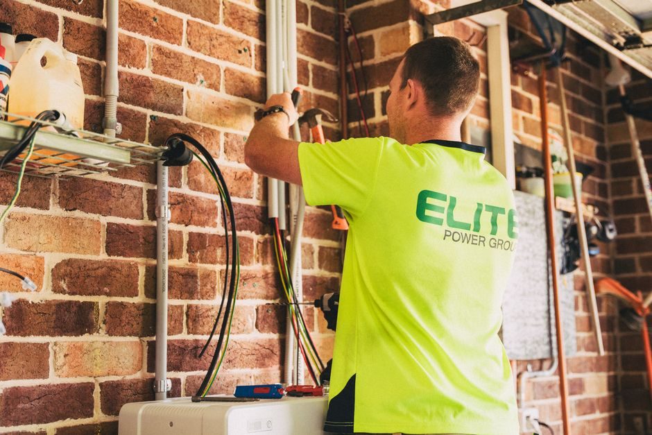
Power cable selection hinges on four binding gates: system voltage class (LV ≤1 kV, MV 5-35 kV, HV 66-500 kV), insulation chemistry (XLPE, TRXLPE, EPR, PILC), installation environment (conduit, direct-buried, tray, submerged), and continuous current rating with appropriate derating factors.
For utility and industrial feeder duty, TRXLPE-insulated medium-voltage cables rated 15 kV to 35 kV cover the majority of new underground distribution builds, while EPR-insulated variants rated 5 kV to 35 kV remain the specified choice for wet, flooded-vault, and water-soaked conduit applications where hydrolysis resistance matters [S2]. The DL/T 2412-2021 industry standard separately governs the silicone insulating oils and polyisobutene fluids (molecular weight 300-1500) used to fill cable terminals and accessories, with explicit performance, packaging, and storage requirements [S3].
Voltage Class and Insulation System Pairing
Insulation system selection must track the system voltage class: XLPE and TRXLPE are the dominant choices for 15-35 kV medium-voltage underground feeders because of low dielectric loss and high emergency overload tolerance, while EPR (ethylene propylene rubber) is preferred for 5-35 kV applications exposed to moisture, heat, or where flexibility during termination is required [S2]. Paper-insulated lead-covered (PILC) cable, although legacy, is still replaced section-by-section during urban grid upgrades, and dedicated PILC replacement cables are manufactured for that retrofit duty [S2].
For cable terminations and accessories, the fill fluid is selected per the rules in DL/T 2412-2021, which covers silicone insulating oils (linear-chain organosiloxane polymers) and polyisobutene with number-average molecular weight between 300 and 1500 [S3]. The standard pulls test methods from GB/T 5654 (dielectric loss factor and relative permittivity), GB/T 507 (breakdown voltage), GB/T 3535 (pour point), GB/T 261 (closed-cup flash point), and GB/T 3536 (open-cup flash point) — meaning the fluid spec is fully traceable to national test methods rather than vendor-only data sheets [S3].
Installation Environment and Wet-Performance Duty
Wet-design distribution cables are explicitly engineered for flooded vaults, water-soaked conduit, and high-water-table direct-buried routes — the failure modes that drive the most MV feeder reliability complaints [S2]. The "field-friendly" cable construction pairs a free-stripping insulation shield with an easy-to-remove insulation layer so that termination and splicing preparation time drops significantly compared with traditional bonded-shield XLPE [S2].
Contamination control during manufacturing is treated as a cable-level performance feature, not a factory housekeeping detail: closed-loop extrusion systems are used to permanently eliminate particulate and moisture ingress sources that would otherwise become insulation-life limiters in service [S2]. For panel builders working downstream, the related discipline of Wiring Duct Selection Criteria: 2026 Spec Map for Panel Builders covers how cable runs are physically supported inside enclosures, while Cable Tray vs Drag Chain Cable: Spec-Driven Selection Map governs the open-route decision.
Conductor, Current Capacity, and Derating
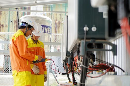
Continuous current rating is set by conductor cross-section (mm² or AWG/kcmil), insulation temperature limit (90 °C for XLPE/TRXLPE, 105 °C for EPR in some specs), and the cumulative derating from grouping, ambient temperature, soil thermal resistivity, and depth of burial. Ampacity tables from IEC 60364-5-52 (LV) and IEC 60502-2 (MV) are the usual reference points for international projects, with NEC Table 310.15(B)(16) governing North American LV feeder sizing. [S2]
Voltage drop is the second binding constraint after ampacity: a 3-5% feeder drop budget at full load is the normal spec band, and on long MV feeder runs the larger conductor cross-section driven by drop often exceeds the ampacity-driven minimum. For runs that exceed ~150 m at 400 V, stepping up to the next conductor size is usually more cost-effective than accepting the higher losses. The basic selection cascade for any LV/MV feeder cable is therefore: voltage class → insulation → conductor size from ampacity → conductor size re-checked against voltage drop → jacket/armour for the environment.
Fire Performance, Jacket, and Code Compliance
For indoor, tunnel, and offshore installations, the jacket and fire-performance stack matters as much as the insulation: LSZH (low-smoke zero-halogen) sheaths per IEC 60332-3 are now the default for occupied buildings and mass-transit tunnels, while fire-resistant (FR) designs meeting IEC 60331 or the relevant UL 2196 / NFPA 130 test method are mandatory for life-safety circuits. The selection logic for that sub-decision is mapped in Fire-Resistant Cable Selection: Spec-First Map for 2026. [S1]
Shielding design splits along construction: tape shield + drain wire is the lower-cost baseline for MV feeder cable, while concentric neutral or longitudinal corrugated copper sheath designs are specified where higher fault-current capacity and better zero-sequence performance are needed. Semi-conductive bedding layers and strippable insulation shields are now standard on TRXLPE constructions to keep termination workmanship consistent [S2].
Comparison: XLPE vs TRXLOPE vs EPR vs PILC for MV Feeder Duty
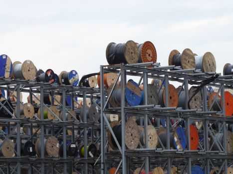
Side-by-side at 15 kV: TRXLPE delivers the lowest dielectric loss and the highest emergency overload ceiling, EPR wins on wet-environment hydrolysis resistance and termination flexibility, XLPE is the cost baseline for dry conduit or tray, and PILC is a legacy retrofit-only choice. On temperature rating, XLPE/TRXLPE sits at 90 °C continuous / 130-140 °C emergency, while EPR typically runs 90-105 °C continuous with a higher short-circuit withstand window. [S2]
On lead time, the field-friendly TRXLPE/EPR constructions from suppliers running closed-loop contamination control offer shorter delivery than industry norm for the same cross-section [S2].
Who Should NOT Default to XLPE
Do not default to standard XLPE for three duty cases: (1) any route through flooded vaults, water-soaked conduit, or high water-table direct-buried soil — EPR or wet-design TRXLPE is the correct pick; (2) any termination or joint that historically had a PIB or silicone oil fill — DL/T 2412-2021 governs the fluid, and the standard also covers storage, packaging, and filling procedure that the installer must follow [S3]; (3) any life-safety or egress route that requires IEC 60331 fire survival — a standard XLPE/LPVC build will not pass.
Industrial buyers who treat cable selection as a single-line commodity buy tend to over-spec on ampacity and under-spec on environment and fire performance. The smarter shortlist logic is: lock the insulation chemistry to the worst-case environment first, then pick the conductor cross-section, then verify termination fluid compatibility per [S3], then close the loop with the appropriate jacket/armour.
Sourcing, Standards, and Watch-Items
Standards to anchor the spec: IEC 60502-2 for MV power cables, IEC 60332-3 for LSZH jacket fire performance, IEC 60331 for fire survival, DL/T 2412-2021 for cable termination insulating oil, and GB/T 5654 / GB/T 507 for the fluid electrical test methods [S3]. For LV control companions, see the Control Cable Selection Guide: Spec Gates for 2026 Sourcing — control cable and power cable are sourced on different ampacity tables and should not be cross-substituted.
Trackable signals for the next sourcing cycle: published revisions of DL/T 5221 (urban MV cable line design), NB/T 10498-2021 (hydro-plant 110-500 kV cable design), and DL/T 5490-2025 (submarine cable line design) — each directly governs the construction spec for adjacent cable categories [S3]. For monitoring the installed cable, see the Power Monitoring System Price and Cost Guide 2026 and the related Isolation Transformer Selection Guide: kVA, Dielectric, and Isolation Class for the upstream/downstream equipment pairing.
Spec-level background on the components involved: power cable, power meter, and power mixer.