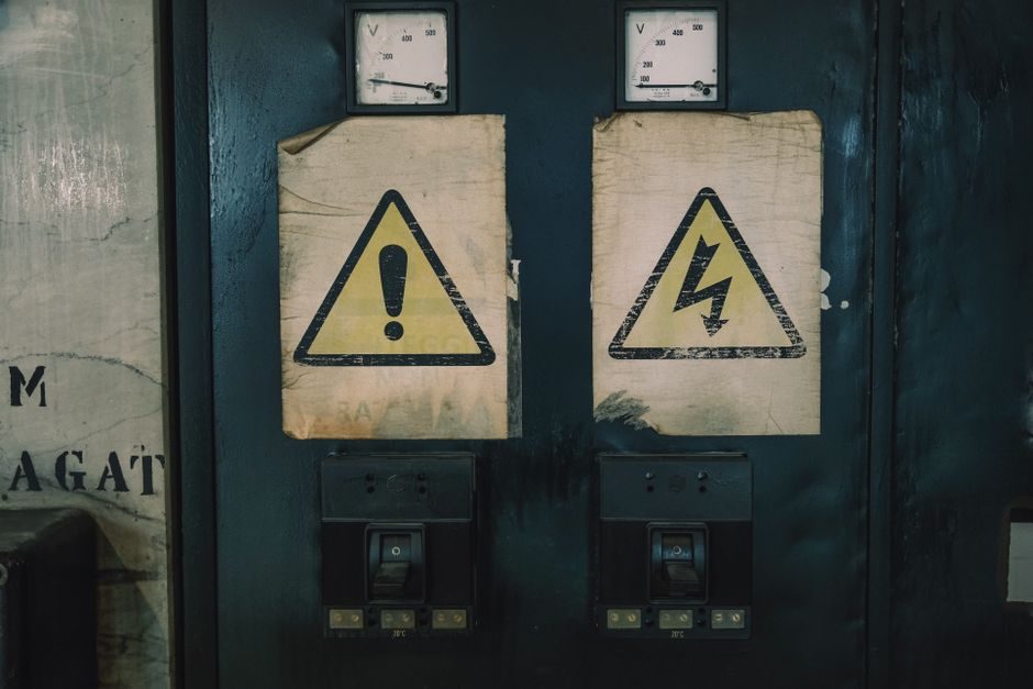
An isolation transformer is a transformer whose primary and secondary windings are galvanically separated by a dielectric barrier, so the secondary floats with respect to earth and the input side until a deliberate bond is made [S1]. The barrier does two jobs at once: it blocks fault-current paths that would otherwise energise a chassis, and it attenuates common-mode noise riding on the line.
Selection is a four-axis problem: apparent power (kVA), primary/secondary voltage and phase count, dielectric withstand between windings and from each winding to core/frame, and the isolation class the end-use standard demands (medical, industrial, test, drive) [S1]. Buyers who fix only kVA and price consistently overspend on the wrong unit or, worse, under-spec the isolation barrier and fail end-of-line Hi-Pot.
What an Isolation Transformer Does, and What It Does Not
Galvanic isolation is achieved by physically separating primary and secondary windings on a common core, with inter-winding insulation rated for a defined AC test voltage (commonly 2.5 kV to 4 kV AC for 50/60 Hz industrial units, higher for reinforced insulation) [S1]. Because the secondary has no metallic return to source ground unless one is added, a single line-to-chassis fault on the load side will not drive current through a person touching the chassis.
It is not a voltage regulator, a filter, or a surge protector. The turns ratio sets output voltage; an isolation transformer with a 1:1 ratio does not change voltage at all, it only separates grounds. Noise rejection is a real side-effect of the barrier and the inter-winding capacitance, but published common-mode rejection is in the 60-80 dB range for typical industrial units and must be verified, not assumed.
kVA, Voltage, and Phase: The Sizing Triplet
Size kVA at 125% of the nameplate sum of downstream loads, not at the running average. Inrush of switching power supplies, motor starters, and DC drive front-ends routinely pulls 3-6x rated current for the first 100-500 ms; an isolation transformer that is exactly matched to running load will saturate and trip on that first cycle [S1]. For drive isolation, the 125% rule is conservative; 150% is common when the drive feeds a motor with a high cyclic load factor.
Match primary and secondary voltage exactly to the system: 480 V delta primary to 208/120 V wye secondary is a standard North American shop-feed configuration; 400 V to 230 V is the European equivalent. Phase count is non-negotiable: a three-phase isolation transformer driving single-phase loads will not balance, and the neutral shift can exceed 5-10% of phase voltage under unbalanced load, which trips 230 V electronics that are rated ±10%.
Isolation Class and Dielectric Withstand: Where the Real Cost Lives

Industrial-grade isolation is typically tested at 2.5 kV AC to 4 kV AC Hi-Pot for one minute between windings and 2 kV AC to 3 kV AC from each winding to ground, with creepage and clearance set by the pollution degree and overvoltage category of the installation [S1]. This is the baseline; medical and measurement-grade builds go further.
Medical isolation transformers used in patient-care areas are designed to UL 60601-1 (and the harmonised IEC 60601-1), with reinforced insulation between primary and secondary, limited earth-leakage current (typically < 300 µA total under normal conditions, < 500 µA single-fault), and a 5 kV or higher Hi-Pot rating. Control and safety lighting transformers fall under IEC 61558-1 / IEC 61558-2-x, with SELV (Safety Extra-Low Voltage) variants limited to 50 V AC or 120 V DC ripple-free output. Specifying one when the other is required is the most common compliance failure on retrofit jobs.
Test-lab and precision-measurement isolation transformers are an underrated segment: they are specified by their common-mode rejection (often 80-120 dB at power-line frequencies, 40-60 dB at 1 MHz) and by the stray capacitance between windings (typically 50-500 pF for shielded units), not by kVA. For more on how isolation interacts with sensitive power monitoring, see the power monitoring system buying guide.
Topology Comparison: Control, Drive, Medical, and K-Factor
Control transformers are small (50 VA to 5 kVA), 1:1 or step-down, and built to IEC 61558-2-2; they are cheap (USD 80-300 at 1 kVA) and the right answer for machine-tool control circuits. Drive isolation transformers sit between the line and a variable-frequency drive, are sized 125-150% of drive input kVA, and include a K-factor rating (K-1 standard, K-4 or K-13 for non-linear loads) to handle the harmonic heating that VFDs push back into the upstream winding. [S1]
Medical isolation transformers are heavier, more expensive (USD 1,200-4,000 at 3-5 kVA), and pass the medical-grade dielectric and leakage tests described above. K-rated transformers for non-linear loads (switch-mode power supplies, LED drivers, IT racks) are derated relative to their kVA nameplate; a K-13 unit at 50 kVA carries roughly 38% of its rating in usable fundamental current, the rest is consumed by triplen and fifth harmonics. Picking a standard K-1 unit for a server room is a textbook 6-12 month thermal failure.
For three-phase drive isolation versus single-phase control duty, the dielectric test, kVA margin, and K-factor dominate the BOM cost in that order; voltage ratio is rarely the deciding factor because most suppliers stock the standard 480-208/120 and 400-230 combinations.
Who Should NOT Specify a General-Purpose Isolation Transformer

Two groups get burned by the generic SKU. First, anyone powering patient-connected medical equipment from a non-medical unit: the chassis-leakage current on a standard 4 kV Hi-Pot industrial transformer is typically 1-3 mA, which is 3-10x the medical limit and will fail any incoming-inspection test under UL 60601-1 [S1]. Second, anyone feeding a VFD or large SMPS cluster from a K-1 transformer: the harmonic heating collapses insulation life from a 20-year design to 2-4 years in field data.
If your load is a single bench instrument on a 230 V outlet, a simple 1:1 medical-grade or audio-grade unit at 100-500 VA is enough; you do not need a K-rated drive transformer, and spending on one will not improve your measurement. Match the isolation class to the load class, not to the largest kVA in the catalogue.
Standards, Tests, and Sourcing Signals
Four standards govern most isolation transformer purchases: IEC 61558-1 (general safety, all units) plus the IEC 61558-2-x part for the specific application family; UL 60601-1 / IEC 60601-1 for medical; UL 1561 or UL 1446 for dry-type construction and insulation systems; and IEEE C57.110 or the K-factor tables for non-linear loading [S1]. The CE / UKCA mark covers the EU/GB low-voltage and EMC directives; a unit without the mark cannot be placed on a control panel that ships into Europe.
On the sourcing side, the 2024-2026 industry signal is shortening lead time on custom voltage ratios and longer lead time on K-rated and medical units. Stock 480-208/120 and 400-230 units ship in 2-4 weeks from most North American and EU distributors; K-13 and medical-grade builds routinely run 10-16 weeks, with the bottleneck at the reinforced-insulation winding and the 100% production Hi-Pot test. Buyers who treat kVA as the only spec and ignore class will see those lead times double when the wrong unit is on the dock.
For reference, dry-type transformer construction details explain why K-factor insulation and 220°C class systems exist, while the power transformer entry covers the larger kVA range that overlaps with drive isolation. Buyers evaluating harmonics should also see the harmonic filter price & cost guide for the upstream mitigation that pairs with K-rated drive isolation.
Shortlist Logic: Matching Isolation Class to Load
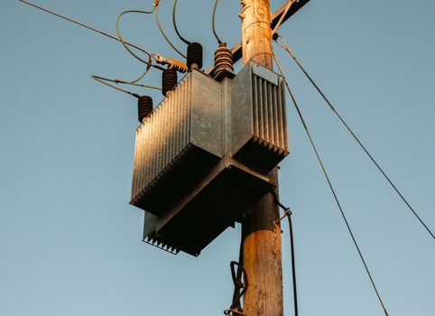
Lead with the load class, not the kVA. For a CNC machine tool or packaging line control circuit, specify a control transformer to IEC 61558-2-2 at 125% of running load, 4 kV Hi-Pot, 50/60 Hz. For a VFD-fed motor, specify a drive isolation transformer at 125-150% of drive kVA, K-4 minimum, 4 kV Hi-Pot, with an explicit harmonic current spectrum on the nameplate. For a medical room, specify a medical isolation transformer to UL 60601-1, with documented earth-leakage current below 300 µA normal / 500 µA single-fault. [S1]
For an instrument bench or test rack, a 1:1 medical-grade or shielded audio-grade unit at 100-500 VA is enough; verify the common-mode rejection in dB and the inter-winding capacitance in pF, both of which matter more than kVA. For a server room, a K-13 transformer sized to 1.15-1.3x the IT load is the floor; below K-13, plan on replacement within 24-36 months.
Verify three things before releasing the PO: the production Hi-Pot test certificate (not a design test), the K-factor or insulation class stamped on the nameplate, and the leakage-current number for medical units. Two of the three will be the difference between a transformer that runs 20 years and one that comes back in 18 months. Watch the 2026 supplier landscape for K-rated and medical-grade lead times, currently 10-16 weeks and the primary schedule risk on any retrofit schedule.
Spec-level background on the components involved: linear guide.