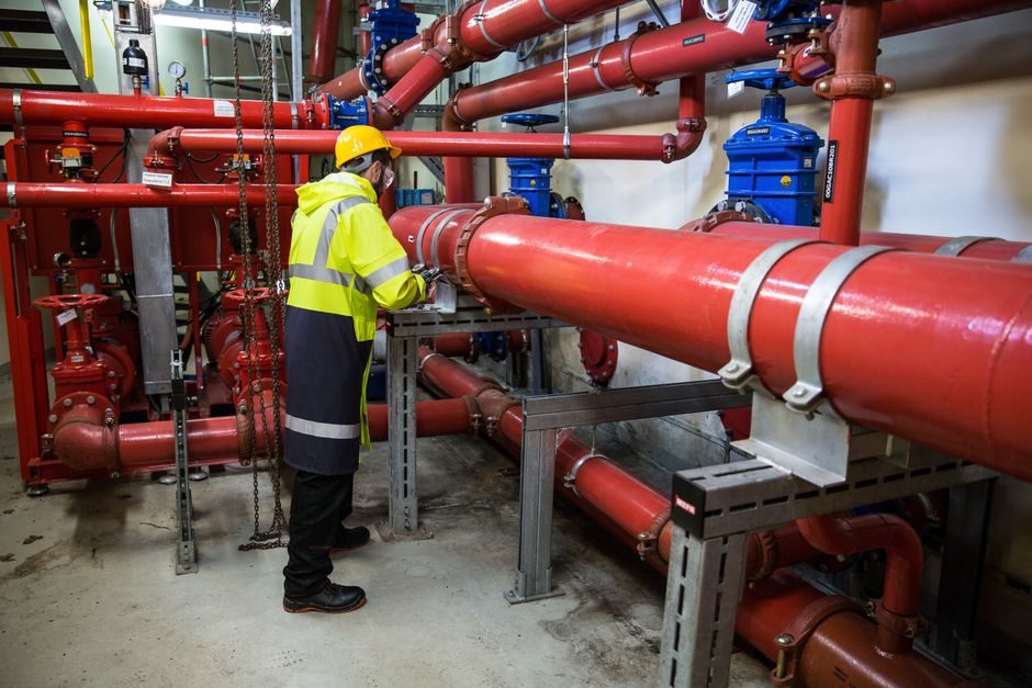
A pressure reducing valve is a self-actuated, normally-open control element that throttles closed as downstream pressure climbs toward the setpoint, holding the outlet within a narrow band regardless of upstream swings or load changes [S2][S3]. In hydraulic networks the element is typically a two-way, spring- or diaphragm-loaded globe that mechanically senses port-B pressure against a reference and modulates opening area proportionally [S3].
Selection fails or succeeds on three numbers: maximum inlet pressure, required flow at the worst-case load, and the maximum permissible outlet pressure. Get the ratio wrong and the valve either chokes, whistles, or fails to fully close [S2]. On process lines that ratio is capped by the manufacturer, typically around 10:1 for direct-acting pilots, which is why high-ratio duties step to a two-stage or pilot-operated arrangement [S1][S2].
How a PRV Regulates: The Setpoint / Regulation-Range Model
Mathworks' Simscape block represents the PRV with a linear or tabulated area-versus-pressure characteristic: opening area drops from a maximum (S Max) at port-B pressure below p Set to a minimum (S Leak) at p Set + p Reg [S3]. The regulation range p Reg is the dead-band the valve needs to transition from full open to full closed; the wider that range, the more stable but the less precise the downstream control [S3].
Thermal-liquid models use the same concept but expressed against a closed-loop network reference rather than atmosphere, so the same block behaves identically whether the working fluid is water, oil, or glycol mix [S4]. In every case the element is normally open and contracts only when downstream pressure approaches the setting — a critical detail when sizing fail-safe behaviour, because loss of downstream sensing line means full-open and re-pressurisation of the downstream branch [S2].
Type Comparison: Direct-Acting, Pilot-Operated, and Piston
Direct-acting diaphragm PRVs are the workhorse for small DN, low-pressure, clean-service duties; they have a single spring-loaded diaphragm sensing the outlet and modulating the plug. Their ΔP ceiling and Cv ceiling are both limited by the diaphragm area, so direct-acting units are rarely seen above DN 50 [S5].
Pilot-operated globe PRVs use a small pilot to hydraulically position the main plug, which is how a 90-21 series unit holds tight control across 250-400 psi and 180 °F (82 °C) in fire-protection service [S1]. The pilot senses the same downstream pressure but strokes the main valve with line-pressure amplification, so the regulation accuracy is essentially set by the pilot spring quality, not the main diaphragm size [S1].
Piston-type PRVs (e.g. Y410/Y416) become the default at DN ≥ 50 in Chinese industrial practice because the piston body tolerates the higher inlet/outlet differential and provides a wider, more linear adjustment range than a diaphragm of equivalent size [S5]. A simple criteria-based comparison:
Direct-acting diaphragm: smallest footprint, lowest cost, typically ≤ DN 50, ΔP ≤ ~10 bar, accuracy ±5-10% of setpoint [S5].
Pilot-operated globe (e.g. Cla-Val 90-21): 250-400 psi class, 180 °F (82 °C) rated, ±1-3% accuracy, fire-protection and city-water mains standard [S1].
Piston PRV (Y410/Y416 family): DN 50 and above, high-ΔP tolerance, adjustable setpoint that holds against large upstream fluctuations [S5].
Sandwich / subplate cartridge: used in hydraulic power units and skid-mounted manifolds where the PRV bolts directly into a manifold alongside a directional valve — limited Cv but excellent for closed-loop, oil-service duty [S2].
Sizing Procedure: From Flow to Cv to Orifice

Step one is fixing the required flow Q at the most-loaded downstream branch and the minimum differential pressure (inlet P1 minus outlet P2) the valve will see in service. Step two converts these into a required Cv using the standard water equation Cv = Q × √(SG/ΔP) for liquids, or the appropriate gas/vapour form where applicable. Step three is derating: the calculated Cv must not exceed 80-90% of the valve's published Cv at 100% lift, because operating a PRV near full lift destroys its regulation authority [S1][S2].
A common miscalculation is to size to nominal flow only. PRVs must be sized for both turndown (minimum flow where the valve can still modulate without chattering) and peak flow (where the residual ΔP still exceeds the regulator's minimum drop, typically 5-15 psi for water service) [S1]. Sizing only to peak flow drives chattering at low loads, while sizing only to low flow drives an undersized valve that cannot pass peak demand without an excessive pressure drop [S2]. For hydraulic-oil service, the same block-model approach is captured directly in simulation: S Max, S Leak, p Set, p Reg, and a tabulated area-vs-pressure curve, with calculation based on linear interpolation between tabulated bounds and nearest-neighbour extrapolation outside them [S3].
Material, Temperature, and Standards Boundaries
Body material is dictated by fluid compatibility first, temperature second. Ductile-iron globe bodies with EPDM or NBR diaphragms cover most water-service PRVs up to about 180 °F (82 °C) [S1]. Stainless or alloy-steel bodies become mandatory above ~200 °C, in steam, or in any hydrocarbon service where NACE MR0175 sour-service rules apply, but check the actual fluid card rather than assuming. The 90-21 series published envelope — 400 psi and 180 °F (82 °C) — is the ceiling for its standard elastomer kit; steam or hot-oil service over that ceiling requires a different diaphragm/bonnet build [S1].
Installation rules are part of the spec. Underwriters Laboratories requires gauges on both sides of a fire-protection PRV, plus a relief valve of at least 1/2 inch on the downstream side with adequate drainage, and the PRV itself may be installed either vertical or horizontal as long as the sensing line is clean and untrapped [S1]. Skip any of these and the listing is void; the PRV may still regulate, but the assembly is no longer UL-listed for fire-service duty. For a broader view of how a PRV sits next to its relief counterpart, the safety relief valve reference is the right counterpart document, and downstream pressure gauge selection rules align with the same up/down-stream gauge pair [S1].
Hydraulic and Mobile Applications
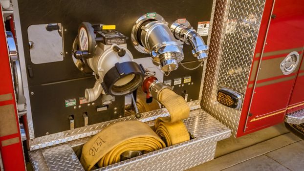
On mobile and industrial hydraulics, the PRV is most often a sandwich or subplate-mounted cartridge that maintains a branch-line pressure, not a system pressure, allowing two or more actuators on a single supply at different regulated pressures [S2]. Patents on hydraulic PRVs emphasise rubber-elastic energising elements and pilot-valve modulation to suppress water-hammer when downstream valves snap shut — a recurring failure mode when the regulator is faster than the actuator [S6][S7]. The Japanese patent literature on hydraulic PRVs focuses on isolation of vibration and friction effects (so-called "vibration-friction abnormal temperature overload imbalance") by pilot-valve operation, which is engineering language for a hunting regulator driven by an under-damped pilot stage [S7].
On a hydraulic power unit the PRV normally sits between the pump line and the directional-control valve, with a separate relief valve as the system over-pressure guard. Treat the two as different functions: the PRV sets a working pressure for a downstream branch, while the pressure reducing valve and safety relief valve together define the operating window and the absolute over-pressure ceiling. For related valve selection, the needle valve sizing and selection guide covers the throttling-duty counterpart where precise Cv and DN matching matter.
Who Should and Should Not Use a Direct-Acting PRV
Pick a direct-acting diaphragm PRV when the line is DN ≤ 50, the fluid is clean water, the inlet/outlet ratio is below 5:1, and accuracy of ±5% is acceptable — building services, irrigation laterals, and small-bore process branches all fit [S5]. Pick a pilot-operated globe (e.g. 90-21) for fire-protection mains, city-water PRV stations, and any duty where the published class rating matches and a listed assembly is required [S1]. Pick a piston PRV (Y410/Y416 family) for DN ≥ 50 industrial water, light oil, or chemical service where the upstream is volatile and the setpoint must not drift [S5].
Do not pick a direct-acting PRV for steam, for any service with entrained particulates, for sour hydrocarbon service without a full NACE MR0175 review, or for any duty where the calculated Cv requires more than 80% of the valve's published maximum — at that point you have a throttling restriction, not a regulator, and the setpoint will not hold [S1][S2]. Do not rely on a PRV for over-pressure protection; the relief-valve-safety-function remains a separate assembly sized to the relevant ASME or local code, not the PRV body [S1].
Commissioning Checks and Field Verification
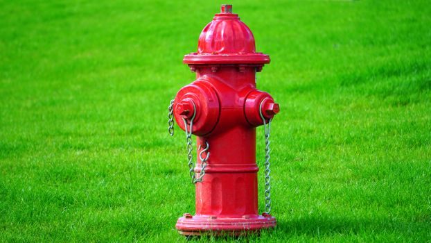
Three numbers must be verified on commissioning: (1) downstream pressure at zero flow equals p Set ± tolerance; (2) downstream pressure at peak flow stays within the published accuracy band; (3) the valve is not operating above 80% of full lift at peak demand [S1][S3]. A pressure calibrator or a calibrated test gauge on each side of the valve is the right tool, and the pressure gauge class should be at least four times tighter than the regulation band being verified.
For hydraulic skid commissioning, the same logic applies using a simulation-matched bench test: sweep downstream pressure from p Min to p Max and confirm the opening area tracks the tabulated curve within the simulation tolerance [S3]. If the field curve is wider than the modelled p Reg, suspect a sticking pilot or a vapor-locked sensing line, not a wrong-sized valve [S1][S7]. A quick-and-relevant cross-reference for adjacent selection logic sits in the needle valve selection map — the throttling-vs-regulating distinction is the one that bites buyers most often.