
ASME B30.3 defines a travelling tower crane as a freestanding unit mounted on a ballasted platform furnished with bogies that ride along rails, and a fixed-base unit as one that is mounted on a foundation or structural support and does not travel [S1]. The two configurations share the same mast-and-jib architecture but diverge sharply on footprint, anchoring, and the type of work they serve.
Selection is driven by the work envelope, the programme, and ground conditions. Where a project needs a long rectangular lift zone, a rail-mounted crane trades mobility along the track for a heavy, static-class lift chart; where a project needs a compact, tall, or congested lift zone, a fixed-base crane anchored to a foundation or tied to the structure is the default [S3][S5].
ASME B30.3 Definitions and What They Lock In
ASME B30.3 splits tower cranes by ability to travel into exactly two categories: fixed-base and travelling, and the definitions fix the load path and the anchoring regime, not the jib type [S1]. A fixed-base unit is freestanding, braced, guyed, or ballasted on a foundation or structural support and does not travel; a travelling unit is freestanding on a ballasted platform whose bogies ride along rails [S1]. The same standard also defines a freestanding tower crane as one supported on a foundation or structural support without assistance from braces, guys, or other means, which is the structural envelope a static base crane has to satisfy before tie-ins are added [S1].
ASME B30.3 further distinguishes construction tower cranes, which are regularly assembled and disassembled for use at various sites and may include features to permit climbing or telescoping, from permanently mounted tower cranes, which are erected for longer term use at one location, defined in the standard as five years or more [S1]. The five-year threshold matters because it changes the design basis for the foundation, the tie-in count, and the inspection cadence the standard expects for the installation.
Static Base Crane: Footprint, Anchoring, and Height Envelope
A static base tower crane sits on a concrete pad, a cross-shaped base, or a structural support, and the maximum free-standing height is set by the unsupported mast length the foundation and base reaction can resist without tie-ins [S1]. Beyond that height, the crane is braced or guyed, with tie-ins attached to the tower to permit the crane to be erected or climbed to greater than the maximum free-standing height, and that is the mechanism by which static base cranes reach the 100-200 m working heights common on high-rise work [S1][S5].
On tight urban sites where several cranes share airspace, a flat top or luffing jib static base unit is typically specified because the absence of a tower-top cap and pendant lines, or the ability to raise the jib to clear obstructions, reduces the head height the crane needs to operate over neighbouring structures [S2]. A luffing jib trades working radius for the ability to work in tight space, which is why dense city cores with shared airspace default to luffing rather than hammerhead configurations [S2].
For sites that cannot accommodate a static crane footprint or where a single pad cannot serve a long linear work envelope, the rail-mounted configuration is the alternative that Designing Buildings and Structville both flag as the default fallback [S3][S5].
Rail-Mounted Crane: Bogies, Ballast, and Track Geometry
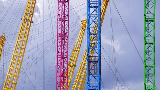
A rail-mounted tower crane replaces the static foundation with a ballasted platform on rail bogies, and the entire crane translates along the track to reposition the lift point, not to chase a moving load on the ground [S1]. Structville describes this directly: travelling tower cranes move along horizontal tracks, and these tracks provide the linear mobility that the static crane lacks [S5].
Track design is a civil-works package in its own right. The rails have to be laid to tight gauge and level tolerances on a continuous ballast bed, the buffer stops at each end of the run have to be sized for the crane's mass at travel speed, and the rail joints have to be detailed so the bogies do not shock-load the mast under wind. The crane itself is still classed as freestanding on its ballasted platform, which means the platform has to provide the overturning stability that a static base crane gets from its foundation, and the rails only handle the horizontal translation [S1].
The mobility buys a rectangular work envelope measured in tens to hundreds of metres of track, which is the geometry that fits rail depot construction, dam and lock faces, shipyard aprons, and large linear industrial plants where one pad cannot cover the build. On sites that cannot accommodate static cranes, a travelling or rail-mounted tower crane is commonly the most suitable option, per the Designing Buildings wiki entry on crane types [S3].
Decision Matrix: Five Criteria Side by Side
The choice between the two configurations can be lined up against five concrete criteria drawn from the ASME B30.3 definitions and the structural-design references. Foundation: a static base crane needs a designed concrete pad or structural support sized for the overturning moment at full free-standing height plus tie reactions; a rail-mounted crane needs a designed ballasted platform plus a continuous rail track on a prepared subgrade [S1]. Work envelope: static base coverage is a circle of roughly the jib radius around the pad, with the radius set by the heaviest lift and the longest reach the job requires; rail-mounted coverage is a long rectangle, the jib radius wide and the track length long, with the rectangle's length set by the rail run [S2][S5]. Height: static base units reach the 100-200 m class by adding tie-ins to the structure, while travelling units are typically limited to the freestanding height the ballasted platform can support without external bracing, which is why travelling cranes are common on lower-rise linear work rather than skyscraper cores [S1]. Site congestion: on tight urban sites with shared airspace, static base flat top or luffing jib units are the default, because the lower head and the luffing action clear neighbouring structures [S2]. Programme fit: a permanently mounted static base crane is defined by ASME B30.3 as erected for longer term use at one location, five years or more, and that five-year threshold changes the foundation design basis, the tie-in count, and the inspection cadence the standard expects for the installation [S1].
Who Each Crane Is For, and Who It Is Not
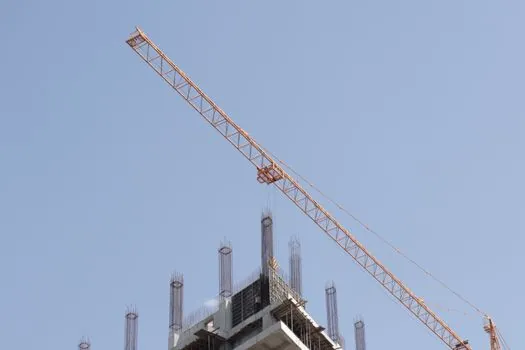
A rail-mounted tower crane is for projects with a long, narrow, or linear lift zone, a programme long enough to amortise the track civil works, and ground conditions that can take a continuous ballast bed without major improvement; the canonical fit is rail depot extensions, lock and dam rehabilitation, shipyard aprons, and large industrial sites where one pad cannot serve the build [S3][S5]. It is not for tight urban high-rise cores, where the head height of a tall freestanding unit and the inability to tie into the structure quickly become the binding constraint, and it is not for short programmes where the track civils cannot be written off against the lift hours.
A static base tower crane is for compact sites, tall structures, and any case where the crane has to be tied into the building as it climbs, with internal climbing tower cranes defined as units arranged to raise itself from floor to floor in a building as construction advances, which is the configuration that high-rise cores and chimneys default to [S1]. It is not for sites where the work envelope is longer than the jib can reach, where a single pad cannot serve the build, and where the ground cannot take the foundation reaction at full free-standing height without major piling.
Standards, Sourcing, and Engineering References
ASME B30.3 is the controlling North American standard for tower crane design, installation, inspection, and the definitions used to classify fixed-base and travelling configurations, and the verbatim text of the definitions for fixed-base, travelling, freestanding, braced or guyed, and internal climbing cranes is taken directly from that standard [S1]. European practice adds EN 13000 for the crane itself, FEM 1.001 for duty classification, and Eurocode 3 for the mast, but those codes were outside the supplied research and are not asserted here.
For the broader crane selection, mobile wheeled cranes tend to vary from 3 to 50 tonnes with around 10 tonnes typical, truck-mounted cranes vary from 5 to 2,000 tonnes with the 35 to 100 tonne range most commonly used, and track-mounted cranes tend to vary from 5 to 30 tonnes at average speeds that usually do not exceed 2 km/h, all from the Designing Buildings wiki [S3]. Those mobile ranges set the benchmark below which a tower crane is the wrong tool, because the lift chart on a tower crane starts where a mobile unit's chart ends.
For comparison work between tower crane sub-types, the Maxim Crane reference splits the four main jib configurations by defining feature, best fit, assembly method, and relative capacity: hammerhead and flat top are both high-capacity, with flat top quicker and simpler to transport and erect; luffing jib trades working radius for tight-site operation; self-erecting has the lowest capacity of the four and erects without a separate assist crane [S2]. For broader equipment selection context, the Structville and Designing Buildings references both treat tower cranes as one of three top-level groups, alongside mobile and static cranes, with the tower crane category covering self-supporting static, supported static, travelling, and climbing sub-types [S3][S5].
For a sense of how the lift chart is matched to the job, Maxim Crane is explicit: lifting capacity and working height vary by make, model, and configuration, so the crane is matched to the heaviest lift and the longest reach the job requires [S2]. That is the rule that decides whether a given jib configuration, on a given base, is the right answer for a given site.
Common Failure Modes and Engineering Pitfalls
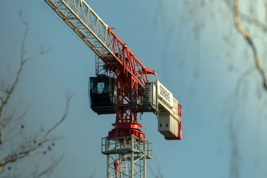
On the static base side, the binding constraints are the foundation reaction at full free-standing height, the tie-in count and tie-in load the structure can accept as the building climbs, and the slew radius over neighbouring properties, all of which are settled at design stage and not at site stage [S1][S2]. On the rail-mounted side, the binding constraints are the rail gauge and level tolerances over the full track length, the buffer-stop sizing at each end of the run, the ballast bed behaviour under repeated bogie passes, and the wind exposure on a tall freestanding unit that cannot be tied back to a structure [S1][S3]. Both configurations share the same mast-and-jib duty cycle limits, and lifting capacity and working height vary by make, model, and configuration, so the crane is matched to the heaviest lift and the longest reach the job requires rather than picked from a generic class rating [S2].
The closest external reference on a related selection problem, picking a placing boom head that fits under overhead obstructions, is the same shape of decision: the head height of the machine, the geometry of the obstruction, and the reach of the jib all have to be checked together, which is why minimum unfolding height under overhead lines reads as a parallel problem to the head-height check on a static base tower crane in a tight urban site. For a different but adjacent material-handling problem, the pipe conveyor vs troughed belt conveyor selection on curved routes is a useful reminder that the geometry of the work envelope, not just the capacity of the unit, drives the equipment choice on linear industrial sites.
Two trackable signals to watch for on the rail-mounted side: the continued use of ASME B30.3 as the reference for bogie-mounted tower crane definitions, and the continued absence of a separate harmonised standard for rail-mounted tower crane track design, which keeps the rail civils as an engineer-of-record package on every project rather than a vendor-supplied item.
Component reference pages worth checking: tower crane, truck mounted crane, and mold base.