Reactive power compensation is the deliberate injection of leading vars (capacitive) to cancel lagging vars (inductive) drawn by motors, transformers, and power-electronics loads, expressed in the standard identity S² = P² + Q² where S is apparent power in kVA, P is active power in kW, and Q is reactive power in kvar [S1].
Utilities charge industrial consumers on a kVA-demand or power-factor-adjusted tariff, so an uncompensated plant running at cos φ = 0.70 pays a noticeably higher demand charge than the same plant corrected to 0.95, while also drawing more current through cables, fuses, and transformers than its active load alone requires [S1][S2]. For buyers in 2026, the buying decision is no longer "do I need a capacitor bank?" but "which compensation architecture, detuning ratio, and controller logic matches my load profile and grid code?"
Compensation Architectures: Passive Banks, Detuned Filters, Active Systems
Three architectures dominate industrial and renewable plant specifications: fixed or automatic passive capacitor banks, detuned (reactor-series) filter banks, and dynamic reactive compensators using thyristor-switched capacitors (TSC), static var compensators (SVC), or STATCOM inverters [S1].
Capacitor banks are the workhorse for stable inductive loads: the reactive rating of each step is expressed in kvar, and stages may be delta- or wye-connected depending on voltage and harmonic exposure; the relationship Q = V² · ω · C links the kvar delivered to the capacitance, line voltage, and system frequency [S1]. Synchronous condensers — over-excited synchronous machines running without a mechanical load — historically served very large industrial sites, but have largely given way to static SVC and STATCOM units where fast response and lower maintenance are required [S1]. Detuned filter banks add a series reactor (typically 5%, 7%, or 14% reactance) to the capacitor step to avoid resonance with the supply impedance and to absorb a specific harmonic order, which is the standard approach on any site with significant variable-frequency drives or large LED/rectifier loads [S2].
Spec-to-Duty Matching: kvar, Response Time, Detuning
The four numbers that drive the 2026 shortlist are total required kvar, switching step size, response time, and detuning factor (p%) [S1][S2]. A buyer should compute required kvar from the target cos φ and the active power: Qc = P · (tan θ1 − tan θ2), where θ1 is the original and θ2 is the target displacement angle, and oversize by 10–15% for voltage rise on lightly loaded days [S1].
Response time separates the architectures: mechanical contactor banks switch in 40–200 ms, thyristor-switched capacitor (TSC) stages in 5–20 ms, and STATCOM IGBT-based systems under 5 ms (full-cycle or sub-cycle), which is why arc furnaces, rolling mills, welding lines, and PV inverter clusters all migrate to active compensation [S1][S3]. Detuning factor p = X_L / X_C is normally 7% for general industrial sites and 14% on heavy-converter sites, and the detuning reactor must be thermally rated for the harmonic current it carries, not just the 50/60 Hz current [S2].
Comparison Table: Four Realistic Options on Decision Criteria
For a 2026 selection, four realistic options can be lined up against the four primary criteria of cost per kvar, response time, harmonic handling, and maintenance burden. Automatic capacitor banks (passive, contactor-switched) score low cost (~€20–40 per kvar installed), slow response (40–200 ms), poor harmonic handling (must use detuned reactors), and low maintenance when type-tested components are used [S2].
Thyristor-switched capacitor (TSC) banks score medium-high cost (~€60–100 per kvar), fast response (5–20 ms), harmonic-neutral when detuned, and low mechanical maintenance because there are no moving contactors [S1]. STATCOM/SVC active systems score high cost (~€150–300 per kvar), fastest response (under 5 ms), excellent harmonic and flicker handling, and medium maintenance tied to the IGBT stack lifespan [S1][S3]. A practical shortlist for arc-furnace duty is therefore a small TSC plus a STATCOM stage sized for the flicker component, while a stable motor plant running three shifts only needs an automatic detuned filter bank [S2].
Who Should NOT Buy the Mainstream Option
Plants with welding robots, container cranes, or large DC drives that swing by hundreds of kvar within a single 50/60 Hz cycle will be poorly served by contactor-switched banks, even at 14% detuning, because the 40–200 ms mechanical switch time leaves a visible flicker envelope and excess cos-phi excursions that grid operators will flag under their technical connection conditions [S2].
Sites with significant 5th- and 7th-harmonic distortion from VFD clusters should not install a plain (non-detuned) capacitor bank, because the supply-inductance-plus-capacitor combination can parallel-resonate at or near a harmonic order and amplify the harmonic voltage rather than absorb it, with documented cases producing capacitor-can failures and nuisance tripping [S1][S2]. For a deeper look at how compensation interacts with on-site metering, the multifunction power meter selection map lays out the controller-side data the regulator needs.
Controller, Protection, and Safety Module Requirements
The 2026 shortlist must include the controller specification, not only the capacitor stage. Modern automatic power factor controllers (PFCs) read the actual cos φ via a current transformer on the main bus, target a settable cos φ (commonly 0.95–1.00 lagging), and switch stages in or out to keep the measured value inside a configurable bandwidth [S2].
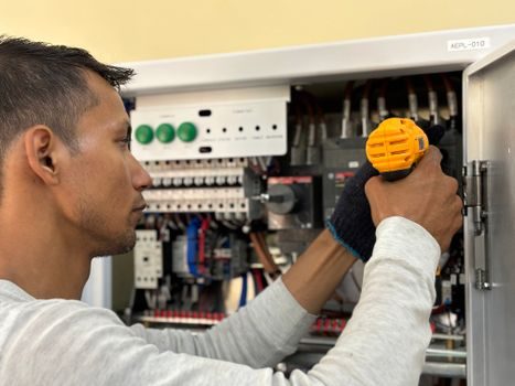
The published KBR multicab system, for example, integrates a temperature-controlled cabinet ventilation to prevent capacitor overheating, uses type-tested quality components, and ships with a secureC safety and maintenance module plus an automatic extinguishing system, with optional detuning reactors available on every cabinet size [S2]. The detuning reactor in a 7% p-filter shifts the parallel-resonance point well below the 5th harmonic so that harmonic amplification is suppressed rather than amplified, and the thermal rating of the reactor must be selected at 130% of the capacitor's rated current to absorb the extra I²R loss at harmonic frequencies [S2]. Buyers should also confirm compliance with IEC 61439 for the assembly, IEC 60831-1/-2 for the capacitors, and the local grid code for the target cos φ, and these requirements should be written into the purchase specification, not assumed [S2]. For a complementary view on the metering side, the multifunction power meter versus compensation spec map walks through which class of meter a compensation cabinet must reference to stay within tariff accuracy.
Standards, Sourcing Signals, and What to Track Next
Two engineering facts anchor the 2026 selection: the apparent-power identity S² = P² + Q² holds for any balanced three-phase system and is the basis for the kvar calculation [S1], and the displacement power factor cos φ — not the true power factor including harmonics — is what most grid operators enforce under their technical connection conditions [S2].
Buyers should also be aware that simulation tooling for STATCOM and SVC dynamic compensation is openly available for offline tuning, including MATLAB/Simulink models of midpoint reactive compensation with SVC and STATCOM stages published as reference implementations [S3]. For context on how compensation costs compare to other grid-edge equipment, the smart meter price and cost guide and the broader reactive power compensation reference provide useful cost and definition anchors when a spec sheet is being audited.
Spec-level background on the components involved: linear guide, and crossed roller guide.